
Table of Contents
Purpose
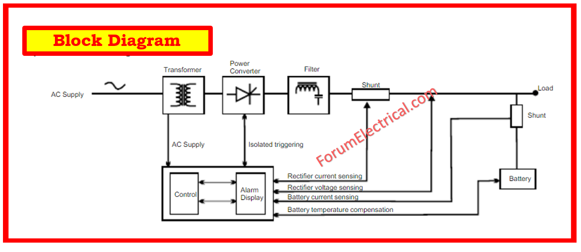
The battery charger will also give DC power to the battery system. Automatically give continuous electrical power within the specified limits & without interruption. The autonomy time in the case of network breakdown shall be decided by the battery capacity.
Battery Supply
These tests are designed to ensure that the board & its components function properly.
This protocol establishes a safe, standardized strategy for the initial inspection, checkout, testing, & data documentation of Uninterruptible Power Supplies (UPS) and Chargers during the commissioning phase.
Reference Document
- Single line diagram
- Schematic diagram/Equipment drawing
Scope
All working sites.
Terminology
Not relevant.
Equipment under Test
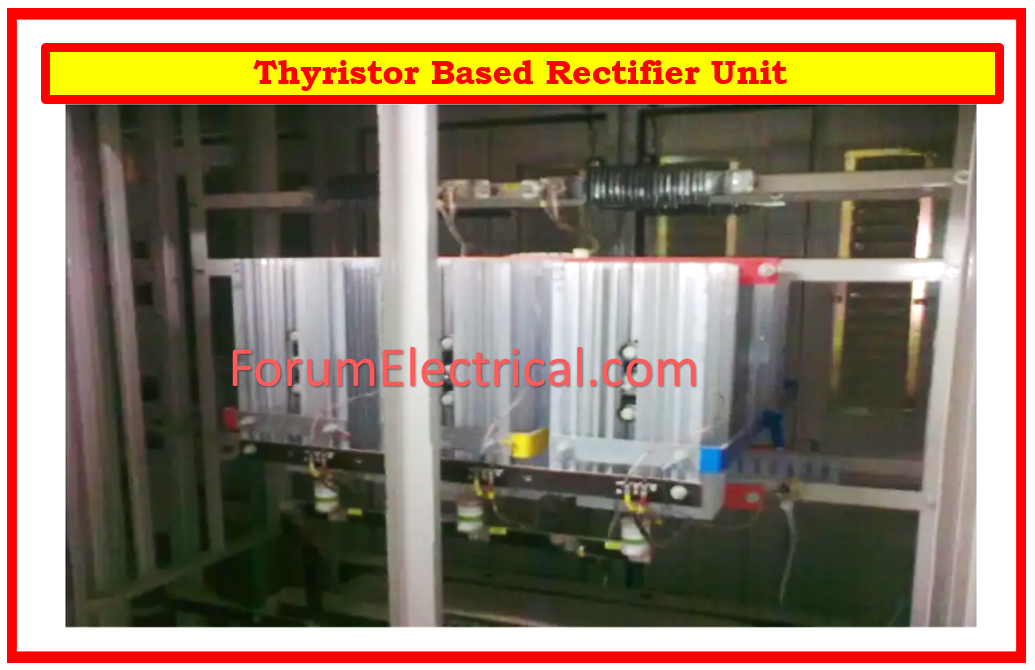
- Thyristor Bridge Battery Charger
- Electronic static switches
- Control Units
- Voltmeter and Ammeter
Test Equipment Required
- Digital multimeter
- Milliohmmeter for continuous measurement.
- Megohmmeter (500V DC)
Preliminary Check
- Ensure battery charger board components are properly marked.
- Ensure that there is no possibility of coming into contact with any electrified equipment before starting work on the system.
- Verify the main busbar & auxiliary circuits (control, monitoring, alarm, & fault) for continuity.
- Verify the grounding busbar’s continuity & connection to the primary earthing system.
- Earthing strands should be used to ensure that panel hinged doors are properly linked to the frame.
- Check door locks for proper operation.
- Open all incomers & load circuit breakers.
- Verify that the connections are secure and that they adhere to the reference drawings.
Electrical Checks
Testing for continuity between both metal parts & ground
- Regarding the evaluation of continuity during this test, it is typically suggested to make use of a milliohmmeter.
Insulation Resistance (IR) Test
- It is advised that these tests be performed prior to connection to ensure that all isolating devices are opened.
- If the cables already have been connected, open the isolating devices before doing any tests.
- Disconnect both the ground sensing device & the control cords.
- Utilizing a 500 V DC megaohmmeter, measure insulation resistance after one minute of electrification between
- Positive and negative busbars with ground.
- Negative and positive busbars with ground.
- Auxiliary circuit & ground.
- Rewire the cables after testing.
System Check
- Verify manufacturer data through visual inspection.
- Proper device and cable labeling
- Easy access
- No damage to device or cable
- Correct cable terminations
- Sealed cable entries in terminal boxes
- Proper protection and grounding connections
- Correct power supply
Mechanical Check
Connections for grounding, cables, and terminal blocks.
Electrical Function Tests
- DC isolators that are open between the battery charger and the consumers and the batteries
- Switch on main supply voltage
- Check voltage and phase sequence
- Switch on battery charger AC side
- Determine the DC voltage in each of the operational modes.
- Check voltage & polarity on both sides of the DC isolator
- Close DC isolator
- Check annunciation
Check Battery Charger Panel prior Energizing
- Connect the battery charger, battery supply cables, or incoming cables from the Main Distribution Board.
- Check for the presence of mechanical guards that prevent inadvertent contact with live parts.
- Open all of the devices that are responsible for terminating outgoing connections.
- Check the distribution board (DB) alarm data and return it to the output terminal blocks.
Check Automatic Transfer Switches
- Check the mechanical and/or electrical interlocks.
- Check the correct polarity.
- With both accessible supplies, confirm the functional checks by the existence of voltage, loss of supply, and restoration of supply in manual & automatic modes.
Establishing into Service
- Check that all relevant protective & signaling devices are operational.
- Voltage measurement, polarity check, and voltmeter reading must be performed for each busbar.
- Following the completion of the related low voltage power lines & polarity tests, all outgoing circuit breakers should be closed as they are required.
- Open the circuit breakers Q1 (input), Q2 (battery output), and Q3 (coupler output), then turn off all automatic circuit breakers.
- Turn ON the 400 V AC input voltage and connect it to the plant.
- Use a voltmeter to measure the connection voltage as well as the rotating field at Q1.
- It is vitally necessary to ensure that the phase rotation sense is clockwise.
- Turn on circuit breakers Q1.
- Turn on circuit breakers Q2.
- After a brief startup phase, the display alternates between showing the unit’s output voltage and total output current.
Record Inspection and Test Data
The results of the inspections and measurements taken during the field test must be reported on the test sheet.


