Battery Testing
Battery testing comprises measuring the voltage, capacity, & other parameters of the battery with the help of a multimeter or another equipment. You will be able to tell whether a battery is defective, weak, or needs to be changed based on the results of the tests performed on the battery.
- Battery Testing
- What is the purpose of Battery Testing?
- What is the Standard for Battery Testing?
- Battery Testing Procedure
- Visual Inspection
- Voltage Measurement
- Self Discharge Test
- Capacity Test
- Internal Resistance Test
- Full Cycle Test
- Rapid Test
- BMS Test
- Coulomb Counting Test
- Read-and-Charge Test
- SOLI Test
- Specific Gravity Test
- Open Circuit Voltage Test
- Load Test
- Why Battery Testing is Important?
What is the purpose of Battery Testing?
Battery testing appears to be valuable to all of us, therefore before we discuss it, we should understand the fundamentals.
Batteries are extremely significant in today’s world since they serve as a power backup storage unit and are portable.
They deliver energy when there’s is no electricity and store it for later use. Batteries have many applications.
They are widely utilized in a variety of applications, including industries, homes, automobiles, mobile devices, offices, laptop computers, and medical equipment.

First, we must define battery testing. It is the technique for determining whether a battery meets Indian (or) International battery standards and performs to its full potential.
Battery testing provides a comprehensive representation of the three primary parameters:
- Capacity (ability to store power),
- Internal Resistance (ability to supply current), and
- Self-Discharge.
The battery’s charge level must be maintained for it to perform properly.
Batteries are highly expensive to purchase, and while UPS batteries are promoted as lasting 9-10 years, we typically have to replace them after 5 – 6 years.
So, battery testing gives us an accurate representation of the battery.
Batteries are frequently available at higher rates if they have met all of the safety standards & testing requirements.
Battery testing provides results for a variety of factors, including battery life and capacity.
What is the Standard for Battery Testing?
Battery testing in accordance with multiple standards, including
Battery Testing Procedure
Visual Inspection
The initial stage is a visual inspection. Check the cell (or) battery.
Examine it for signs of damage, such as leaks, cracks, rust, or swelling.
You may also need to smell the rechargeable battery. A leaky cell usually smells appealing.
Voltage Measurement
When the battery is rested, its voltage represents the level of charge in an open circuit. Voltage alone cannot predict a battery’s state of health (SoH).
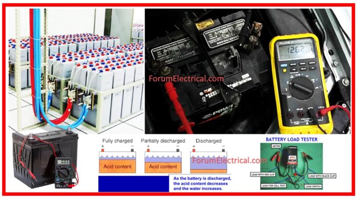
Connect multimeter probes to battery & measure the voltage.
The voltage should fall across the
- LVC (Low Voltage Cutoff) &
- HVC (High Voltage Cutoff)
specified in the cell or battery’s datasheet. For NMC (Nickel-Manganese-Cobalt), this will range between 2.5 V & 4.2 V per cell.
An LFP (Lithium Iron Phosphate) cell (or) battery will have a voltage between 2.5 V and 3.7 V.
If it is much lower or greater than these figures, there is an issue.
Self Discharge Test
Fully charge all of the cells you plan to test.
Take note of the voltage once you remove them from the charger.
Leave the cells to settle for two weeks and ensure that they are stored at a consistent temperature.
After that time has gone, retest the voltages of each cells; any that have declined by greater than.1V should be avoided.
Capacity Test
A capacity test is a very effective way to determine how useful a battery will be because it shows how much energy it can store.
It can also help determine the general condition of the battery through comparing the energy it can really store to the energy it is rated to store.
A 5Ah cell may only hold 4Ah, resulting in 80% of its claimed capacity. At this point in time, the cell has completed its life cycle and is no longer functioning.
Internal Resistance Test
This is the most important performance indicator for battery cells.
Calculating internal resistance will tell you how healthy your battery is and how much electricity it can safely & practically supply.
A high internal resistance (over 50 mΩ) will prevent the battery from delivering maximum power due to a significant voltage drop under load.
This also called an impedance test (or) ohmic test.
Full Cycle Test
A full cycle includes charging, discharging, & charging in order to determine a chemical battery’s capacity.
This gives the most accurate measurements & calibrates smart battery to address tracking inaccuracies, but the process is time-consuming and stressful.
Rapid Test
Typical test methods include
- Time Domain (activating the battery with pulses to examine ion flow in Li-ion) and
- Frequency Domain (scanning a battery with numerous frequencies).
Advanced rapid-test technologies require complex software that have battery-specific properties & matrices that function as lookup tables.
BMS Test
Battery Management System (BMS) test calculate State of Charge (SoC) by measuring voltage, current, and temperature.
Coulombs are also counted by Li-ion battery management systems.
Coulomb Counting Test
The Full Charge Capacity (FCC) reading is immediate, but the data becomes incorrect with usage, & the battery needs calibration after a full cycle.
Read-and-Charge Test
A charger with RAC technology scans the battery SoC using an internal filtering algorithm & followed by counts the coulombs to charge the battery.
RAC (Reconfiguration-Assisted Charging) requires a one-time calibration for every battery model; cycling an adequate pack generates this parameter, which is saved in battery adapters.
Cadex developed the RAC technology.
SOLI Test
The State-of-Life Indicator (SOLI) calculates battery life by counting total number of coulombs that a battery can deliver over its lifetime.
A newly installed battery starts at 100% capacity; delivered coulombs reduce the number till the allotment is depleted & a battery replacement is necessary.
The entire scale is determined by multiplying the result of the calculation of the coulomb count of one cycle by the cycle count that was provided by the manufacturer. This calculation depends on production requirements (V, Ah).
Cadex developed SOLI, which may be utilized in wheelchairs, medical equipment, traction, and UPS, either when new or as a retrofit. Wireless communication enables fleet management.
| Testing Method | Lead Acid | Nickel Based | Li-ion | Primary Battery | |
| Analog | Voltage | Estimates SoC in the open circuit condition. Temperature & active materials of a battery. | |||
| Ohmic Test | Identifies heat failure and other faults; cannot estimate capacity. | Correlation occurs between resistance and capacity. | Low capacity cannot influence resistance. | Resistance refers to SoC, which is specific to each battery type | |
| Full Cycle | Use sparingly for large batteries. | Recommended for smaller batteries. | Not Available | ||
| Rapid Test | Time domain tests resistance and ion flow, whereas frequency domain reads capacity. | Internal resistance has some correlation with SoH. | High efficiency enables the time and frequency domain. | Resistance check using a lookup table for various batteries is possible. | |
| BMS | Voltage, current, and temperature sensors to monitor the battery. | Not practicable owing to inefficiencies. | High efficiency allows for coulomb counting. | SoC based on voltage | |
| Digital | Coulomb Counting | The low charge & discharge efficiency making this unworkable. | Unsuitable due to ineffectiveness & significant self-discharge. | Suitable with the majority of lithium batteries. LiFePO exhibits significant self-discharge. | Used for clinical applications with better results |
| Read-and-Charge (RAC) | Not practicable due to low charge & discharge efficiency and significant self-discharge. | Powered by great efficiency | Not Available | ||
| SOLI | Determines battery life depending on provided energy. A newly installed battery starts at 100%. Drawing energy depletes the coulomb allowance, necessitating battery replacement at zero. Can be used with any battery. | ||||
Specific Gravity Test

Note: Do not add water prior to testing (Flooded batteries only)
- Before taking a sample, fill & drain the hydrometer two to four times.
- The hydrometer should contain enough electrolytes to fully support the float.
- Take a reading and restore the electrolyte to cell.
- The OCV of tested cell will be specific gravity reading + .84.
Ex: 1.22 s.g. + .84 = 2.06V
To verify another cell, follow steps 1–3 above.
- Check all of the cells in battery.
- Change the vent caps & clean up any electrolytes that may have leaked.
- Adjust temperature measurements to 80°F:
- Add.004 to measurements for every 10° over 80°F (6° above 26°C)
- Subtract.004 for each 10° below 80°F (6° below 26°C)
- Comparing the readings.
- Check the charge status using the “Open Circuit Voltage” chart below.
- The OCV of a measured cell is the specific gravity (s.g) reading +.84.
Ex: 1.22 s.g. + .84 = 2.06V
- The values should be within (or) above factory specification of 1.280 ±.005.
If a specific gravity values are low, perform the instructions below:
- Check & record voltage levels.
- Charge the battery(s) to 100% capacity.
- Take exact gravity readings again.
- If specific gravity values are still low, follow the instructions below:
- Check the voltage level(s).
- Apply the equalization charge. The proper approach is described in the Equalizing section.
- Take specific gravity (s.g) readings again.
If a specific gravity reading is lower than the manufacturing specification of 1.280 ±.005, it could indicate one of the following conditions:
- The battery is old & nearing its final stage of its lifespan.
- The battery had been discharged for an extended period of time.
- The electrolyte was lost because of spillage (or) overflow.
- A weak or abnormal cell is developing.
- Prior to testing, the battery had been overwatered.
- Batteries with conditions 1–4 should be evaluated by an expert (or) removed from service.
Open Circuit Voltage Test
For reliable voltage measurements, batteries must be idle (no charging or discharging) for a minimum of eight hours, ideally 24 hours.
- Disconnect all loads from battery.
- If feasible, test the specific gravity. The OCV of tested cell will be s.g -specific gravity reading +.84.
Ex: 1.22 s.g. +.84 = 2.06 V.
- Use a DC voltmeter to measure the voltage.
- Check the charge condition.
- Charge battery if it shows 0% to 75% charge.
If the battery records beneath temperature compensated readings after charging, the following may occur:
- The battery was allowed to discharge for an extended period of time.
- The battery has a faulty cell.
- Batteries in such conditions must be taken to a professional for further testing or withdrawn from service.
Load Test
Repeat the same method for VRLA (Valve-Regulated Lead-Acid) DRY CELL batteries & flooded batteries:
- Recharge if OCV falls below 75%.
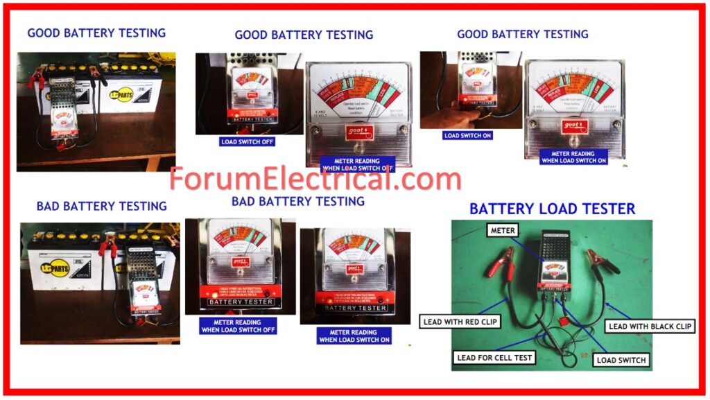
- Apply a load of 3 to 3.5 times, 20-hour rate using an adjustable load tester.
- Maintain the load for 15-20 seconds. While under load, the voltage should stable at or above 9.6 volts.
- If the battery has a CCA (Cold Cranking Amps) rating, apply a load equivalent to ½ of the rating for 15 seconds. While under load, the voltage should stable at or above 9.6 V.
- To conduct a more thorough test, implement a load which equals 100% of rated CCA (or) at 5–6 times the 20-hour for 30 seconds. While under load, the voltage should stable at or above 7.2V.
- If the voltage falls below 9.6 V (7.2 V for 100% CCA), recharge and repeat the test. If the voltage falls below 9.6 V (7.2 V for 100% CCA test), the battery should be replaced.
Why Battery Testing is Important?
The testing of batteries is essential because it assures the dependability, efficiency, and safety of the battery.
Through routine testing, potential problems can be identified, optimal performance can be maintained, battery life can be extended, and unexpected power outages can be avoided.
It is essential for applications in important areas such as backup power, renewable energy storage, & transportation, where the performance of the battery has a direct impact on the efficiency and safety of the system.


