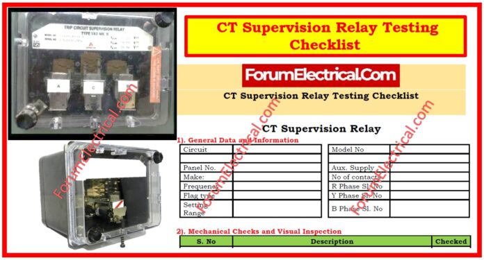
What is a Supervision Relay?
A supervision relay, also known as a trip circuit supervision relay (TCS), continuously monitors the functioning of important control circuits such as circuit breaker trip circuits and detects faults such as auxiliary voltage loss or circuit breaking, assuring reliable operation.
How does CT Supervision Work?
The CT supervisor function monitors phase currents. If one of the 3 phase currents falls below the Imin value while another exceeds the Imax setting, the function will trigger an alarm after the operation delay.
What is a CT Switch Relay?
The CT switching relays are primarily used for the signal amplification, electrical isolation, switching between coil and contact voltage potentials, and adding switching contacts.
The output relay is energized by applying control supply voltage.
General Data & Information
This section contains important information about the CT Supervision Relay, including the model number, panel number, auxiliary supply voltage, make, number of contacts, frequency, flag type, & setting range.
The serial numbers for the R Phase, Y Phase, & B Phase are captured as well to guarantee that the relay is correctly identified and verified.
Mechanical Checks & Visual Inspection
A complete mechanical inspection confirms that the relay is structurally sound and appropriately fitted.
The following steps must be completed:
- Inspect for physical damage or faults.
- Verify connections using authorized drawings.
- Check the tightness of all electrical connections.
- Check the labeling & location of the ferrules.
- Check the equipment lists for the completeness.
- Check that the serial number on the relay matches the serial number on the case.
Electrical Tests
Preliminary Test
The preliminary test assures that the relay is ready for operation by checking basic electrical functions:
- Check test switch isolation for the R, Y, and B phases.
- Ensure that the CT bus shorting contacts are tested and appropriately configured.
Relay Burden Test
The relay burden test determines the power consumption of the relay under various operation conditions.
The test comprises determining the relay’s DC voltage, DC current, & burden in both no-operation and operating settings.
Typical burden values are:
- For 48/54V operation or no operation: 1.3W / 4.86W
- For 110/125V operation or no operation: 3.0W / 4.37W
Pickup Test
The pickup test measures the voltage at which the relay activates & deactivates.
This test confirms that the relay has the necessary pickup voltage tolerance (+/-5%) and drop-off/pickup ratio (>85% after a 3-second delay).
The test is carried out with voltage settings of 2V, 3V, 5V, & 9V across the R, Y, & B phases.
Timing Test
The timing test evaluates the relay’s actual running time at twice the pickup voltage (2xVs).
The operating time for all three phases (R, Y, & B) is predicted to be within 3 seconds (+/-5%).
Final Settings
This part stores the relay’s final current settings based on the test findings, ensuring proper operation under actual load levels.
Pickup Test (Final Verification)
A final pickup test is performed to check the relay’s pickup voltage, drop-off voltage, and drop-off/pickup ratio for all three phases (R, Y, and B).
Functional Test
The functional test ensures that the CT supervision relay functions properly. The following checks are completed:
- Check that all relay contacts are functioning and work as planned.
- Measure the resistance of each output contact to ensure correct conductivity.
- Observe the operation of the relay flag indicator.
Conclusion
Performing these checks ensures that the CT supervision relay performs properly, identifies CT faults, and protects the electrical system.
Regular testing and maintenance help to avoid malfunctions, assuring the overall safety & stability of the power system.


