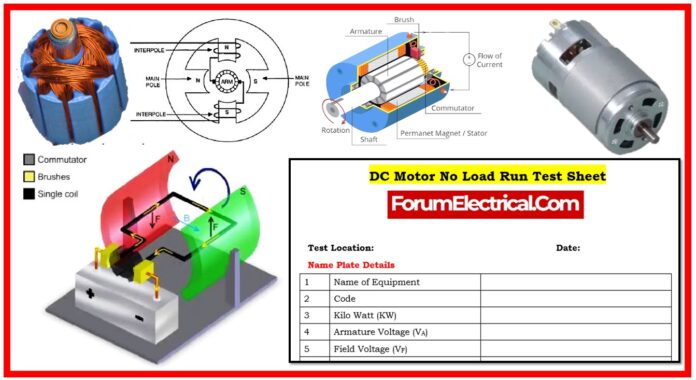
What is DC Motor?
A DC motor is a device that transfers electrical energy from direct current (DC) into mechanical energy. A DC motor’s input electrical energy is the direct current, which is transformed into mechanical rotation.
When a DC motor is activated, it produces a magnetic field within the stator. This magnetic field interactions with magnets on rotor, which causes it to rotate. To ensure that the rotor rotates continuously, the commutator feeds current to the motor’s wire windings via brushes attached to the power source.
This post includes a checklist for testing the functioning of a DC motor. It covers
- Inspecting the motor,
- Wiring, and
- Protection systems
to assure safe operation.
- Winding Resistance,
- Insulation Resistance,
- Current,
- Voltage,
- Temperature, and
- Vibration
are all important measurements to take during a load run test.
The procedure also includes safety precautions such as turning off electricity sources and posting warning signs. The purpose is to thoroughly inspect the motor and ensure that all readings & components are normal before permitting operation.
Purpose
A DC motor no-load run test is an important method for evaluating the motor’s performance and ensuring its suitability for use. This procedure contains a complete guidance for carrying out the test, including essential parameters to monitor, safety precautions, and a checklist to use during testing.
Test Procedure
Nameplate Details
Before starting the test, obtain and record the motor’s nameplate information to ensure accuracy in the assessment.
The key parameters include:
- Name of Equipment
- Code
- Kilowatt Rating (kW)
- Armature Voltage (VA)
- Field Voltage (VF)
- Armature Current (IA)
- Field current (IF)
- Duty Cycle
- Connection Type
- Degree of Protection
- Insulation Class and Frame
- Serial Number
- Manufacturer
Pre-Test Checklist
Proper preparation is essential for an efficient no-load run test.
The following steps need to be verified:
- Approach & Housekeeping: Keep the testing space clean and accessible.
- Motor Condition: Make sure the motor is not running & determine whether it is linked or decoupled.
- Power Availability: Verify the main power & control supply availability.
- Mounting & Foundation: Inspect the motor’s mounting type (foot or flange), make sure the foundation bolts are secure, and look for any damage to the base or legs.
- Terminal Box: Check that the insulated terminal block (or) terminal box is intact & undamaged.
- Earthing: Double-check that the motor & local control station (LCS) are both earthed properly.
Electrical Testing
To certify the condition of the motor, do the following electrical tests:
- Winding Resistance: Determine resistance for both the armature (A1-A2) and the field windings (F1-F2).
- Insulation Resistance (IR): Utilize a 500V insulation tester to get IR values. All measurements must exceed 5 MΩ to be considered valid.
- Armature to Earth (A–E)
- Field to Earth (F-E).
- Armature to Field (A–F)
If the IR values are low, utilize a space heater or an external heater to dry the windings.
Functional Verification
- Validate that all logic and protection features are operational.
- Set the selector switch to LOCAL (or) REMOTE mode based on operating requirements.
Test Execution
- Breaker and Control: Rack in the feeder (or) breaker & turn on the control power MCB. Check the “OFF” indicator on the feeder.
- Initial Checks: Monitor the motor’s current, noise, & vibration levels during startup.
Monitoring Parameters
During the no-load run, gather the following parameters.
Load Run Details
- Starting Current: Note the starting current & time.
- Voltage and Current: Record the line voltage & current readings at regular intervals.
Temperature Measurement
To maintain thermal stability, measure and log the temperatures of the motor body, bearing (DE & NDE), and winding at regular intervals.
Vibration Measurement
Measure vibrations in the vertical (V), horizontal (H), & axial (A) directions. Compare the measured values to the permitted limits.
Post-Testing Activities
After the no-load run, inspect the motor for any abnormal warmth, noise, or vibrations.
Documentation
Prepare a complete test report that includes recorded data for all parameters, as well as comments on any deviations discovered during the test.
Ensure that the document is validated and signed by both the site & testing engineers.
Pre-Test Checklist
This organized procedure assures that the DC motor is adequately tested and ready for its intended use.


