- What is PSC in Electrical?
- What is the purpose of PFC test?
- What is done during PFC and PSC Tests?
- Why PSC and PFC are done?
- How is PSC and PFC Performed?
- Prospective Short Circuit Test Procedure
- Prospective Fault Current Test Procedure
- Advantages of PSC and PFC Tests
- Difference between PSC and PFC Test
- PSC Test vs PFC Test
What is PSC in Electrical?
PSC – Prospective Short circuit Current
The current that is predicted to flow in a circuit if the line & neutral cables are shorted is known as the prospective short circuit current (PSC).
It is the most significant current that can flow through the system. Therefore protective devices should be able to safely breach it.
The PSC (Prospective Short Circuit Current) is the maximum current that can travel between line and neutral conductors in a single-phase supply (or) between line conductors in a three-phase supply.
A PSC test determines the current that would flow in the case of a short circuit across the live conductors. That is, line & neutral in a single-phase system, or line to line/line to neutral in a three-phase arrangement.
What is the purpose of PFC test?
PFC – Prospective Fault Current
Prospective Fault Current (PFC) is the term used to describe the maximum amount of current that will flow under fault conditions.
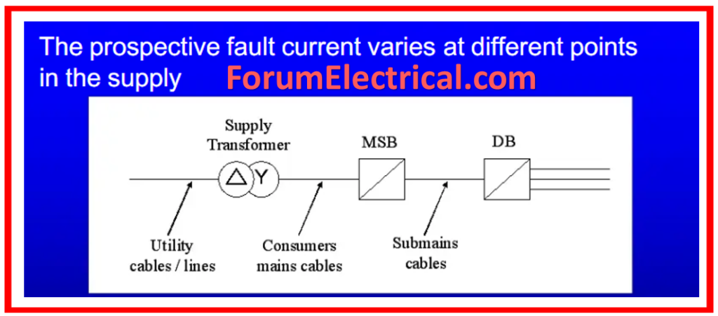
The PFC will always be higher near the installation’s source because the impedance/resistance is lowest there. So, as a rule, if it’s not excessive at the mains, it should be acceptable everywhere else.
This is because as we go away from the origin, resistance increases, causing it to decrease. (Ohm’s law I = V/R).
In the case of an earth fault, also known as a Line to Earth fault, a PFC test will determine the maximum current that can flow through the system.
The outcome of the test might be observed through calculation, ascertained through analysis to the appropriate electrical board, or measured through the utilization of a Loop Test Machine (Loop Tester).

What is done during PFC and PSC Tests?
PSC depends on the voltage and impedance of the supply system.
Electrical current can range from a few milliamperes in a separate extra-low voltage (SELV) system to hundreds of thousands of amperage (amps) in major industrial power systems.
Standard household mains installations typically have a few thousand amps.
To prevent the circuit from a failure,
- Circuit breakers and
- Fuses
should have an interrupting rating that exceeds the short-circuit current.
When a large electric current is interrupted, an arc forms.
If the breaking capacity of a fuse (or) circuit breaker is exceeded, the arc will not be extinguished.
The current will persist, causing damage to equipment, fire, or explosion.
PFC is carried out at the installation’s origin, such as the main switch or other switchgear that is directly connected to the tail of the electrical distributor’s metering equipment.
A measurement taken at a point in the installation other than its origin, such as a component of switchgear powered by a distribution circuit, will not represent the maximum value for the system.
Particular caution should be given during the testing process, as fault conditions tend to be most severe at the source of an installation, where this test is done. During these tests, the
- Earthing conductor,
- Main protective bonding conductors, and
- Circuit protective conductors
should all be connected as they would be during normal operation, since the existence of these as well as any other parallel paths to earth can reduce the impedance of the earth fault loop, increasing the level of prospective fault current.
The PSC will be greater than the PFC. When doing a loop impedance test, the circuits
- Prospective Fault Current &
- Short Circuit Current
are automatically determined.
The computation employs a notional circuit voltage rather than the real circuit voltage.
Why PSC and PFC are done?

It is essential that we undertake testing to ensure that the protection devices installed in a circuit are rated at the appropriate breaking capacity.
In a household installation, 6000A (6kA) rated MCBs are commonly installed in a circuit.
If a residential premises is particularly close to a supply substation and the property’s measured exterior impedance (Ze) is 0.03Ω, Ohm’s law forecasts that 7,666A can flow in the case of a 230V supply fault.
This may create problems if the switch gear is only rated for 6000A.
How is PSC and PFC Performed?
The nominal supply voltage utilized in the calculation is set automatically based on the real circuit voltage.
The voltage values that the instrument utilizes are as follows:
| Actual Voltage | Nominal Voltage |
| < 75 V | 55 V |
| ≥= 75 V & <150 V | 110 V |
| ≥= 150 V & <300 V | 230 V |
| ≥=300 V | 400 V |
Prospective Short Circuit Test Procedure
Step-1: To test for short circuits, use a PFC tester or a multipurpose tester like Megger. Ensure the supply is on but Main Switch is turned off.
Step-2: Connect the test leads to the incoming side of Main Switch, with one on Line and another on Neutral.
Step-3: Push the TEST switch and take note of the value (kA).
Step-4: For three-phase installations, each phase is tested independently & the measured reading (Line 1 to Neutral, then Line 2 to Neutral, and finally Line 3 to Neutral) is doubled.
Step-5: Certain test meters require the third lead (typically green) to be connected to Neutral during the test. Please follow the instructions provided by the manufacturer of the test meter.
Prospective Fault Current Test Procedure

Step-1: When using a PFC tester or the PFC function of a multi-functional tester like Megger, ensure that the supply is ON and the Main Switch is OFF.
Step-2: Connect the test leads to the Main Switch’s Line, Neutral, and Earth terminals.
Step-3: We press the TEST switch and take note of reading (kA).
Step-4: For three-phase setups, each phase is examined independently, & the measured reading is doubled (L1 – N – CPC, L2 – N – CPC, L3 – N – CPC).
Step-5: After obtaining these values through the measurements outlined above, we will select the greatest number and record it on the Electrical Installation Certificate (EIC) as a measurement of PFC.
Step-6: The PFC value obtained is compared to the breaking capability of all protective devices in the installation. The breaking capacity of protective devices must exceed the value of PFC.
Advantages of PSC and PFC Tests
- They provide accurate results because it is live testing.
- The test is simple, and few calculations are required.
- Increased employee and third-party safety.
- Reduced insurance premiums.
- Asset management & tracking systems.
- Minor equipment repairs are completed on-site to minimize downtime.
Difference between PSC and PFC Test
PSC Test vs PFC Test
| Category | PSC (Prospective Short Circuit Current) Test | PFC(Prospective Fault Current) Test |
| Definition | The PSC test determines the maximum current that might flow via a short circuit at a given location in an electrical installation. | The PFC test determines the maximum current that can flow during any fault state, not just short circuits, but also line-to-ground faults. |
| Purpose | The primary objective is to make sure that the electrical system & its protective devices (such as circuit breakers & fuses) can safely interrupt & endure the highest potential short-circuit current without causing damage or a fire. | This test verifies that the entire system is protected against various fault conditions by ensuring that protective mechanisms work properly to isolate the fault and safeguard the system. |
| Measurement | This test usually entails connecting a testing instrument to the supply conductors at the place of interest & simulating a short circuit. The device uses the circuit’s impedance to calculate the prospective short circuit current. | Similar to PSC, this test uses a testing instrument to determine the possible fault current. It may, however, comprise multiple types of fault conditions, depending on the installation & testing requirements. |
| Focus | PSC concentrates on the current that would flow in a complete short-circuit scenario with minimal impedance, which is typically only the impedance of the conductors itself. | PFC has a wider application than PSC since it includes many fault conditions in addition to the basic short-circuit condition. It takes into account the impedance of the complete fault path, including protective devices, grounding, & other components. |
| Usage | PSC is commonly used to evaluate short-circuit protection capabilities. | PFC is employed to conduct a thorough assessment of fault protection in an electrical installation. |


