
Circuit diagrams are the blueprints for all systems in the field of electrical and electronic engineering. To effectively understand these diagrams, you must first understand the connector and earthing symbols.
Connectors help to create detachable junctions between circuits or wires, while grounding (earthing) ensures safety, stability, & protection against electrical problems. Both forms of symbols have a significant impact on circuit dependability and clarity.
The following table lists the most frequently employed electrical wiring schematic symbols for the connectors that comply with the IEC and BS Electrical Symbols. These connectors include plug & socket, coaxial, terminal, and earth connections.
Below is a thorough table outlining some of the most popular and important connector & earthing symbols utilized in electrical schematics:
| Symbol | Symbol Name | Description |
| Plug Male | The symbol “Plug (Male)” represents a male plug connector with protruding pins that fit into a socket. Common in power supply connectors & instrumentation. | |
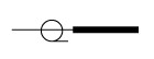 | Coax Plug Male | The symbol “Coax Plug (Male)” refers to a male coaxial connector used for transmitting RF signals, such as in antenna systems (or) TV connections. |
 | Wire Connections (Two Wires) | Two electrical wires are joined at a junction. A dot is often used to indicate where they intersect. |
| Socket (plug female) | Socket (Plug Female) refers to a female plug that accepts male pins. Used in wall outlets and device ports. | |
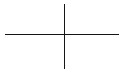 | Wires Crossing (Not Connected) | To avoid confusion, this sign depicts two wires crossing without making an electrical connection, which is typically depicted by a “bridge” or minor jump. |
| Slow Operating Relay – Delay On | The symbol represents a relay with a delay-on feature, which means it activates after a set amount of time. Frequently utilized in timing circuits and protective relays. | |
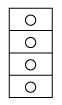 | Terminal Block | The Terminal Block symbol represents a multi-point connection device that links many wires in control panels (or) junction boxes. Useful for organizing wiring. |
 | Terminal Connector | A terminal connector connects a wire to another device or panel. Used for field wiring and testing. |
 | Wire Connections (Crossed) | Two wires are crossed and connected, indicated by a little dot at the intersection. |
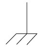
 | Earth Connection | This is the most popular earthing sign. It indicates that the circuit is connected to the earth ground for safety & fault current dissipation. |
 | Noiseless Earth | Used to describe a low-noise or clean ground, particularly in analog (or) sensitive signal systems. Prevents interference from the power ground. |
 | Protective Earth | The Protective Earth (PE) sign connects the metallic body of the equipment to the earth, preventing electric shocks in case of insulation failure. Marked on appliances. |
 | Chassis Earth | Grounds the equipment to its chassis rather than the earth. Establishes a common basis within a device |
 | Equipotentiality | A symbol indicating that different sections of a system are connected to the same electrical potential, preventing voltage variances for safety and uniformity. |
Significance of Earthing & Connector Symbols
- By understanding these symbols, circuit diagram misunderstandings can be prevented.
- Shocks, fires, and equipment damage are avoided with proper earthing.
- These symbols are used by technicians to identify faults and perform maintenance.
- These adhere to global standards (such as ANSI and IEC) to guarantee design compatibility.
Conclusion
Despite their seeming simplicity, earthing symbols and connectors are the most important components in the construction of a circuit that is both safe and accurate.
By becoming proficient with these symbols, you will improve your technical literacy & ensure that your electrical profession is safer.
This is true regardless of whether you are constructing a simple lighting system (or) an advanced control panel.


