1). What is an Induction Motor and how does it work?
An induction motor is an alternating current electric motor in which power is delivered to the rotor through electromagnetic induction rather than direct electrical connections.
It works on the principle of electromagnetic induction, which states that a spinning magnetic field in the stator creates current in the rotor.
The combination of the magnetic field & induced current provides torque, which causes the rotor to rotate.
Induction motors are utilized in industrial applications because to their durability, simplicity, and low cost.
2). How is the construction of an Induction Motor?
An induction motor has two primary parts:
Stator: The stator is the stationary portion that contains coils of insulated wire arranged in slots around a laminated iron core. An alternating current (AC) current that travels through the stator windings brings about the generation of a magnetic field that rotates.
Rotor: The revolving component, which can be of two types: squirrel cage rotor (or) wrapped rotor. The squirrel cage rotor is made up of short-circuited bars connected by end rings. The wound rotor has windings coupled to external resistances via slip rings.
3). What is a Synchronous Motor?
A synchronous motor is an AC motor that runs at a constant speed and is synced with the frequency of the AC power source.
Unlike induction motors, synchronous motors have an independent excitation on the rotor, which is typically supplied by a direct current source.
The rotor’s magnetic field locks onto the stator’s revolving magnetic field, allowing the motor to run at synchronous speed without slippage.
4). What is Slip in an Induction Motor?
Slip is the difference between the synchronous speed of the stator’s rotating magnetic field & the rotor’s actual speed, represented as a percentage of synchronous speed. The formula is as follows:
Slip (%) = [(Synchronous Speed-Rotor Speed)/ (Synchronous Speed)] x 100
Slip is required for torque generation in an induction motor because it generates relative motion between the rotor & the magnetic field.
5). Why are Starters used to start Induction Motors?
Starters are utilized in induction motors to reduce inrush current during startup. When an induction motor begins, it consumes a large amount of current (6-8 times the rated current) since the rotor is at rest and there is no back EMF.
This high current can cause damage to the motor windings & other electrical components. A starter assists to gradually increase the voltage while decreasing the starting current, so safeguarding the motor.
6). Which motor is used in fans?
Ceiling and table fans typically employ single-phase induction motors. These motors are dependable, simple, and cost-effective for domestic applications that demand consistent speed.
7). Why do we use starters for a DC motor?
Starters are used with DC motors to limit the initial starting current. A DC motor at rest has very little resistance in the armature winding, & applying full voltage at startup would result in a significant current flow, which could damage the motor windings.
A starter connects a resistance in series with the armature circuit & progressively reduces it as the motor accelerates, resulting in a regulated increase in current and voltage.
8). What are the advantages of DC motors over AC motors?
The primary advantage of DC motors is their ability to give accurate speed control across a wide range of speeds.
This makes them excellent for use in applications that require variable speed, such as electric cars, elevators, and cranes.
Additionally, DC motors offer a strong starting torque, which is useful in many applications where loads must be shifted from rest.
9). What is the Ward-Leonard System?

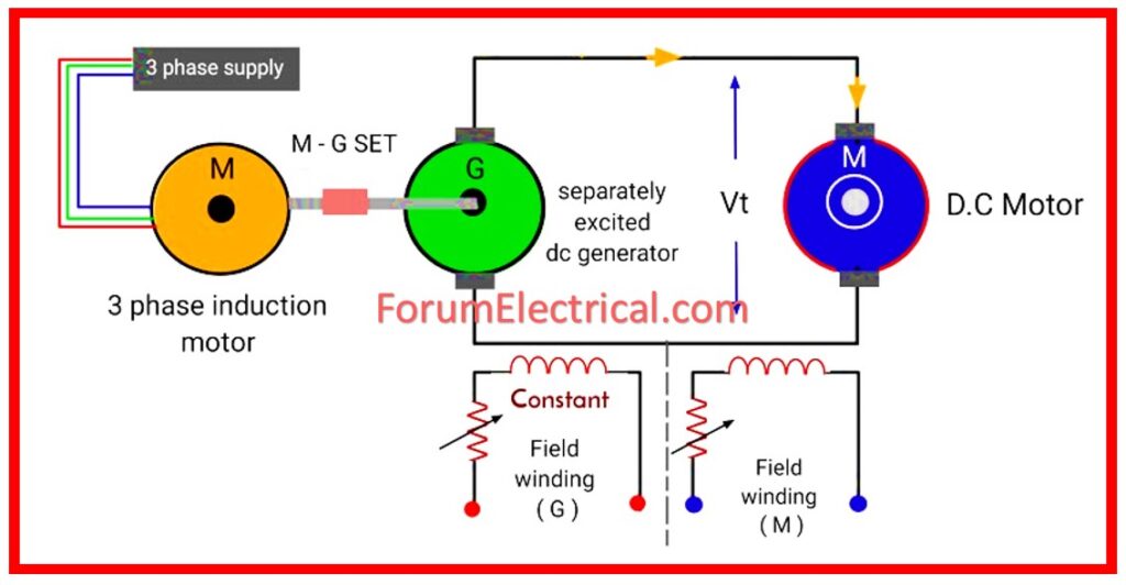
The Ward-Leonard system is a method of speed control for DC motors, particularly in conditions that require a wide range of speed and precision control. It is made up of a DC motor with a variable DC generator to control its field.
The generator’s output is controlled by modifying its field current, which controls the voltage provided to the motor and, consequently, its speed.
This technique was commonly employed in elevators, cranes, & rolling mills before to the widespread adoption of current electronic controls.
10). What happens if the direction of current at the terminals of a series motor is reversed?
In a series motor, the field and armature windings are connected in series, so when the current at the terminals is reversed, both the field and armature currents reverse as well.
Because the magnetic field and armature current are reversed, the torque remains constant, & the motor continues to rotate in the same direction.
11). What is a Circuit Breaker?
A circuit breaker is a device that automatically shuts the flow of electricity in an electrical circuit when a fault occurs (such as an overload or short circuit), therefore protecting the circuit from damage.
12). What types of circuit breakers are there?
The primary types of circuit breakers are:

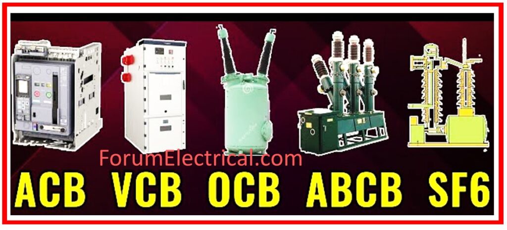
- Air Circuit Breaker (ACB)
- Miniature Circuit Breaker (MCB)
- Oil Circuit Breaker (OCB)
- Vacuum Circuit Breaker (VCB)
- SF6 Circuit Breaker (Sulfur Hexafluoride gas).
13). What are ACB, MCB, OCB, and VCB?
ACB: Air Circuit Breaker – utilizes air to extinguish arcs.
MCB: Miniature Circuit Breaker – prevents overloads and short circuits in low-power systems.
OCB: Oil Circuit Breaker (OCB) employs oil as an arc extinguishing medium.
VCB: Vacuum Circuit Breaker (VCB) – employs a vacuum to extinguish the arc.
14). What is the function of a fuse?
A fuse protects electrical circuits by disconnecting the connection when too much current runs through it, preventing damage from overheating or fire.
15). How do fuses work?
A fuse is a tiny wire that melts when an excessive amount of current goes through it. Melting the wire breaks the circuit, stopping the flow of current & averting system harm.
16). What is Faraday Law of Electrolysis?
Faraday’s Law of Electrolysis states that the amount of chemical reaction (or substance deposited) during electrolysis is proportionate to the amount of electricity (charge) that passes through the electrolyte.
17). What is the Electrolyte of a Battery?
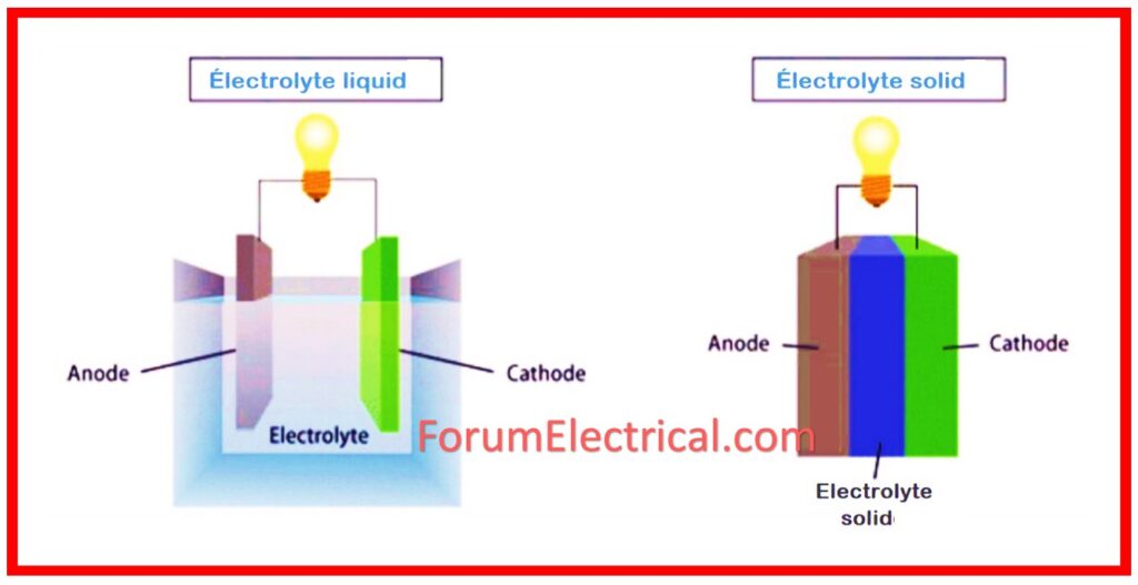
An electrolyte in a battery is the medium (often liquid, paste, or gel) that allows ions to move between the anode and cathode, generating energy.

18). What is a Primary Cell?
A primary cell is a type of battery that is intended to be used only once and then discarded because it cannot be recharged.
19). What is a Secondary Cell?
A secondary cell is a rechargeable battery that can be recharged & reused (such as lead-acid or lithium-ion batteries).
20). What are the main components of a Lead-Acid Battery?
The primary components of a lead-acid battery include:
- Lead dioxide (PbO2) – Positive Electrode
- Sponge lead (Pb) – Negative Electrode
- Sulfuric acid (H2SO4) – Electrolyte
21). What are Thermistors?
A thermistor is a resistor whose resistance changes considerably with temperature. They are frequently utilized as temperature sensors.
22). Why do thermistors have a negative temperature coefficient?
A Negative Temperature Coefficient (NTC) thermistor’s resistance decreases with increasing temperature. This happens because increasing temperature gives electrons greater energy to move, lowering resistance.
23). What is a Semiconductor?
A semiconductor is a substance whose electrical conductivity falls between that of a conductor & that of an insulator. Its conductivity can be adjusted by adding contaminants or changing circumstances such as temperature.
24). What is an Intrinsic Semiconductor?
An intrinsic semiconductor is a pure semiconductor (such as silicon or germanium) that has no impurities added. Its conductivity is determined primarily by temperature and the material’s inherent qualities.

25). What is an Extrinsic Semiconductor?
Extrinsic semiconductors are semiconductor materials that have had their electrical characteristics altered by the addition of impurities (doping). Extrinsic semiconductors include
- N-type semiconductors and
- P-type semiconductors,
which are produced by doping silicon with elements such as phosphorus (or) boron.


