
- What is a transformer?
- Importance of a Transformer
- Transformer Components and Construction
- Working principle of a transformer
- Transformer Types
- Transformer Classification based on Voltage Level
- Transformers Classification based on Core Material
- Transformer Classification based on Usage
- What is an Ideal Transformer?
- Ideal Transformer EMF Equation
- Turn Ratio
- Efficiency of the Transformer
- Energy Losses in the Transformer
- Application of the Transformer
What is a transformer?
A transformer is a static electrical machine that transfers alternating current (AC) power from one circuit to another at a constant frequency, but the voltage level can be changed, which means the voltage can be increased or decreased as needed.
It works according to Faraday’s Law of Electromagnetic Induction, which states that “the magnitude of voltage is directly proportional to the rate of change of flux.”
Importance of a Transformer
Electrical power is typically generated at 11KV. AC power is transmitted over long distances at very high voltages, such as 220 kV or 440 kV, for economic reasons. As a result, at the generating stations, a step-up transformer is used.
For safety reasons, the voltage is now stepped down to different levels by step down transformers at various substations to feed power to various locations, and thus power is used at 400/230 V.
- If (V2 > V1), the voltage on the output side is increased, and this is referred to as a step-up transformer.
- If (V2 V1), the voltage level on the output side is decreased, and the transformer is known as a step-down transformer.
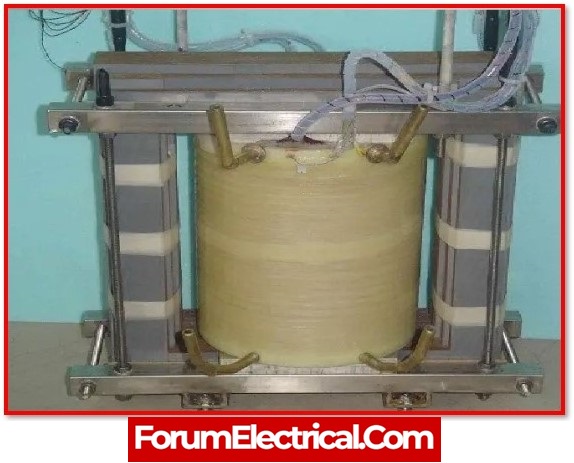
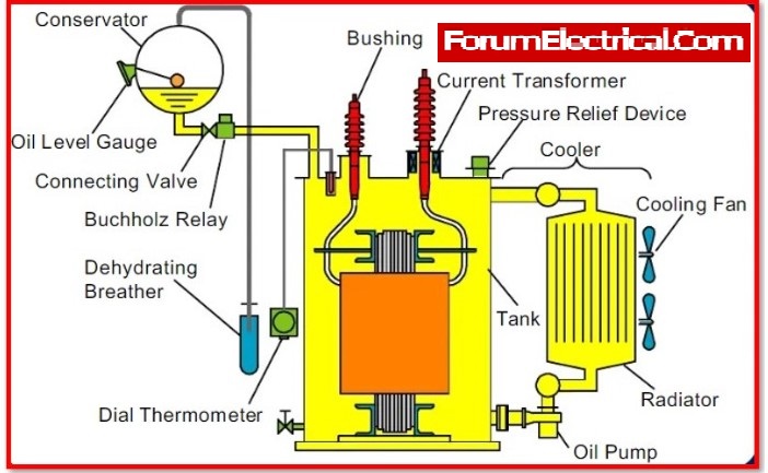
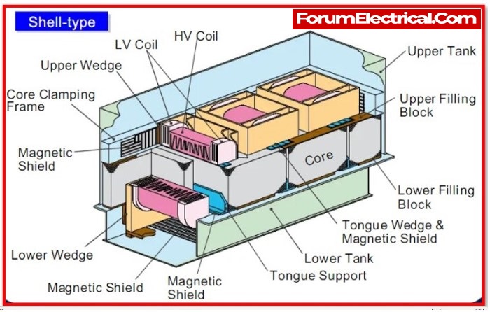
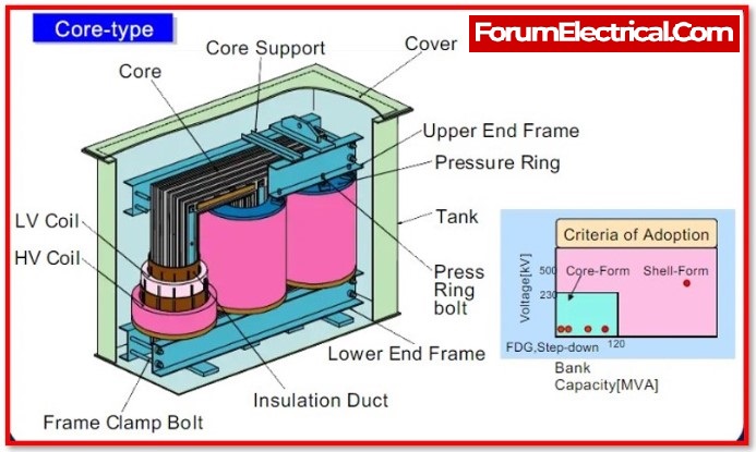
Transformer Components and Construction
A transformer’s three primary components are:
- Primary Winding
- Magnetic Core
- Secondary Winding
1). Primary Winding
Transformer’s primary windings when coupled to an electrical source, results in the production of magnetic flux.
2). Magnetic Core
The magnetic flux that is produced by the main winding, will flow through this low-reluctance path linked to the secondary winding, which will result in the formation of a closed magnetic circuit.
3). Secondary Winding
When the flux that is created by the primary winding passes through the core, it will eventually connect up with the secondary winding.
This winding generally winds on the same core as the other windings, and it provides the output that is initiated from the transformer.
Working principle of a transformer
The working of a transformer is based on the principle of mutual induction between the primary and secondary windings, also known as coils, which helps in the conversion of energy from one circuit to another.
In general, the alternating voltage is received by the transformer’s primary coil. The alternating current that follows the coil creates a constantly changing and alternating flux that encloses around the primary winding.
Then there is another coil, or secondary coil, which is close to the primary coil and is linked to it by some alternating flux. As the flux changes continuously, an EMF is induced in the secondary coil by Faraday’s law of electromagnetic induction.
A current will flow if the secondary side circuit is closed, and this is the most basic operation of a transformer.
Transformer Types
Transformer Classification based on Voltage Level
Based on the operating voltage, there are primarily two types of transformers.
- Step-down Transformer
- Step-up Transformer
1). Step-down Transformer
A step-down transformer converts the primary voltage to a lower voltage across the secondary output. The primary side of a step-down transformer has more windings than the secondary side.
As a result, the overall secondary-to-primary winding ratio is never greater than one.
Step-down transformers are used in electrical systems that distribute power over long distances and operate at extremely high voltages to ensure low loss and cost-effective solutions.
A step-down transformer is used to convert high-voltage supply lines to low-voltage supply lines.
2). Step-up Transformer
In step-up transformer, the secondary voltage is increased from the low (low rated) primary voltage. Because the primary winding in this type of transformer has fewer turns than the secondary winding, the primary to secondary winding ratio will be greater than one.
Step-up transformers are commonly used in electronics stabilisers, inverters, and other devices that convert low voltage to much higher voltage.
A step-up transformer is also used in electrical power distribution. High voltage is required for applications connected to power distribution.
A step-up transformer is used in the grid to raise the voltage level prior to distribution.
Transformers Classification based on Core Material
In the power and electronics industries, different types of transformers are used depending on the core materials, which are:
- Iron Core Transformer
- Ferrite Core Transformer
- Toroidal Core Transformer
- Air Core transformer
1). Iron Core Transformer
The core of an iron core transformer is made up of multiple soft iron plates. The iron core transformer has extremely high flux linkage due to its strong magnetic properties.
As a result, the iron core transformer is extremely efficient. Soft iron core plates are available in a variety of sizes and shapes. E, I, U, and L are some common shapes.
2). Ferrite Core Transformer
A ferrite core transformer employs one due to its high magnetic permeability. This type of transformer has extremely low losses in high-frequency applications.
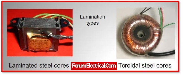
3). Toroidal Core Transformer
Toroid-shaped core materials used in transformers include iron core and ferrite core. Toroids, which have a ring- or donut-shaped core material, are widely used due to their excellent electrical performance.
The ring form produces very low leakage inductance while producing extremely high inductance and Q factors.
4). Air Core transformer
An air core transformer’s core material is not a true magnetic core. Air is only used in the air-core transformer flux linkage.
An air-core transformer’s primary coil generates alternating current, creating an electromagnetic field all around it.
Transformer Classification based on Usage
Different types of transformers provide unique purposes. Thus, transformers can be classified as follows based on their desired use:
- Power Transformer
- Measurement Transformer
- Distribution Transformer
- Pulse Transformer
- Audio Output Transformer
1). Power Transformer
A larger power transformer is used to transfer the energy to the substation or the general electrical supply.
This transformer acts as a link between the main distribution grid and the power generator. Power transformers are classified into three types based on their power rating and specifications:
- Large power transformer,
- Small power transformer and
- Medium power transformer
2). Measurement Transformer
A measurement transformer is also known as an instrument transformer. This is yet another measurement tool commonly used in the power domain.
A measuring transformer is used to separate the primary power and convert the current and voltage in a smaller ratio to the secondary output.
3). Distribution Transformer
The distribution transformer acts as a step-down transformer, converting high grid voltage to the voltage required by the end user, which is typically 110V or 230V.
The distribution transformer may be smaller or larger in size depending on the conversion capacity or ratings.
4). Pulse Transformer
The pulse transformer is a popular PCB-mounted transformer that generates electrical pulses with consistent amplitude. It is used in a variety of digital circuits where isolated pulse generation is required.
5). Audio Output Transformer
The audio transformer is another common transformer in the electronics industry. It is specifically used in audio applications where impedance matching is required.
What is an Ideal Transformer?
An ideal transformer has no losses at all, including no core losses, copper losses, or other transformer losses. This transformer is considered to be completely efficient.
A transformer with zero losses, including zero core losses, copper losses, and additional transformer losses, is an ideal transformer. It is considered that this transformer is entirely effective.
When developing the ideal transformer model, it is assumed that the transformer’s core is loss-free and that its windings are totally inductive.
The transformer also has no leakage reactance. This shows that there is a 100% flux connection between the transformer’s primary and secondary windings. However, there must be some inductive resistance in every winding, which causes a voltage drop and I2R loss.
The windings of a model of an ideal transformer are thought to be perfect (completely inductive), meaning that they have no resistance.
Ideal Transformer EMF Equation
Np be the number of turns in the main winding and Ns be the number of turns in the secondary winding. When an alternating current voltage is applied to the transformer main coil, the current generated generates an alternating magnetic flux that connects to the secondary coil and generates an emf.
The value of this emf is determined by the number of turns in the secondary coil. Consider a perfect transformer with zero primary coil resistance and all flux in the core connecting both primary and secondary windings.
The flux linkage in each turn in the core at time t due to the current in the primary coil when the voltage Vp is applied to the primary coil.
The secondary induced emf or voltage (s) with Ns turns is then calculated.
Es = -Ns x dø/dt…………… (1)
Furthermore, the alternating flux creates a reverse emf in the main. That’s all there is to it.
Ep = -Np x dø/dt…………… (2)
In addition, for an ideal transformer, Ep=Vp
If the secondary is an open circuit or the current drawn from it is moderate, Es=Vs.
Vs is the voltage across the secondary coil. Equations (1) and (2) can thus be written as
Vs = -Ns x dø/dt….. (3)
Vp = -Np x dø/dt….. (4)
From equations (3) and (4).
Ns/Np = Vs/Vp….. (5)
The above equation is referred to as the Transformer equation or the Transformer formula.
To obtain the previous relationship, the following three assumptions are used:
- The electrical resistances of the primary and secondary coils are negligible.
- The flux connectivity to both the primary and secondary coils is the same, which means that very few fluxes escape from the core.
- The secondary current is negligible.
Turn Ratio
The turn ratio of a transformer determines whether the secondary coil has more or fewer windings than the primary. The number of windings on a primary coil is “Np,” and the number of windings on a secondary coil is “Ns,” which represents the number of turns.
If the transformer is perfect or 100 percent efficient, the power input and output will be equal (no energy losses).
IsVs = IpVp….. (6)
Equations (5) and (6) by combining,
Vs/Vp= Ns/Np=K Ip/Is
The preceding equation defines the turn ratio, K.
This is the case if the secondary coil has more turns than the primary coil (Ns>Np), and the voltage is stepped up (Vs>Vp).
This type of setup is known as a step-up transformer.
A step-down transformer has a secondary coil with fewer turns than the primary coil (Ns<Np).
Efficiency of the Transformer
A transformer’s efficiency is also referred to as its commercial efficiency. It is denoted by the letter “. A transformer’s efficiency is defined as the ratio of output (in W or kW) to input (in W or kW).
As a result, the transformer’s efficiency can be expressed as follows:
Efficiency (η) = (Output Power / Input Power)
The above equation can be applied to an ideal transformer with no transformer losses and complete transfer of input energy to output.
As a result, if transformer wastes are considered and the transformer’s efficiency is evaluated across all practical states, the following equation is commonly used.
Efficiency (η) = ((Power O/P) / (Power O/P + Losses)) × 100%
(or)
Efficiency (η) = (Power i/p – Losses) / Power i/p × 100
= 1− (Losses/ i/p Power) × 100
Energy Losses in the Transformer
In the previous equations, an ideal transformer was used (without any energy losses). However, some energy losses do occur in actual transformers for the reasons listed below:
1). Flux Leakage
Because some flux leaks from the core, not all primary coil flux reaches the secondary coil.
This is caused by an inadequately designed core or the presence of air holes in the core.
It can be reduced by wrapping the primary and secondary coils over each other. It can also be reduced if the core is properly designed.
2). Windings Resistance
Because the wire used for the windings has some electrical resistance, heat generated in the windings wastes energy. In high current, low voltage windings, these are reduced by using thick wire with a high conductive substance.
3). Eddy Currents
Eddy currents are created in the iron core by the alternating magnetic flux, resulting in energy losses through heating. The impact is reduced by using a laminated core.
4). Hysteresis Loss
The alternating magnetic field reverses the magnetization of the core during each AC cycle. Heat is lost in the core due to hysteresis loss, which is minimised by using a magnetic material with a low hysteresis loss.
Application of the Transformer
The following are some of the most common transformer applications:
- Increasing or decreasing the voltage level in an alternating current circuit to ensure proper operation of the circuit’s various electrical components.
- It prevents DC from flowing from one circuit to the next.
- It divides two distinct electric circuits.
- The voltage level at the electric power plant must be increased before transmission and distribution can take place.
