")
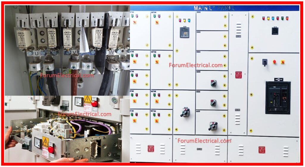
The Factory Acceptance Testing (FAT) procedures for Low Voltage Motor Control Centers (MCC), Switchboards (SWBD), & Switchgear Panels (SWGR) is essential to ensure all electrical panels and equipment fulfill design and safety standards.
- Scope
- General
- Inspection Test
- In-Process & Visual Inspection
- Final Inspection Test
- Mechanical Operation Test
- Continuity Test: Control Wiring & Power Cables
- Functional Operations Test
- High Potential (Hi-Pot Test)
- Insulation Resistance (Megger) Test
- Power Cable, Buses Insulation & Isolation Test
- Acceptance Criteria
- Conclusion
During manufacture, these methods test and inspect equipment for mechanical, electrical, & operational integrity.
The equipment is tested according to NEMA and ANSI standards to ensure it is functional, reliable, & meets quality standards before installation.
Scope
To set up the procedures for the test and inspection – Switchboard (SWBD), Switchgear (SWGR), and low voltage MCC panels
General
The typical factory tests and inspections carried out during the production of industrial control equipment are described in the summary that followed.
Each component of low voltage equipment is examined and tested to ensure that it complies with ANSI and NEMA requirements.
IEC standards, like as IEC 60439-1 for low-voltage switchgear & control gear assemblies, provide as guidelines for the design and testing of switchboards, motor control centers, and switchgear panels.
Type testing and other equipment-destructive tests are not included in the tests. To confirm the availability of test facilities & qualified personnel, QC must be consulted for any additional manufacturing tests beyond those mentioned in the method statement.
In addition to confirming the physical arrangement of assembly as well as workmanship, the mechanical adjustment of parts and components, & the sequencing & functional operations of the control systems, these tests and inspections are carried out on manufactured products to ensure that the equipment complies with the design and job specification requirements.
The test and inspection procedures are carried out in compliance with engineering standards and manufacturing quality control.
The techniques, procedures, and requirements for material control and product manufacturing are covered by these standards, together with the operational test and workmanship inspection requirements.
The necessary quantitative & qualitative acceptance standards are included in the requirements for every test and inspection procedure.
According to the checklist, trade individuals, and materials marking, these requirements are confirmed.
Results of tests and inspections are recorded and assessed.
Inspection Test
Inspection tests will be conducted in two stages.
1). In-Process Inspection
2). Final Inspection Testing
In-Process & Visual Inspection
These inspection tests will be carried out during the manufacturing cycle to ensure proper & correct workmanship and materials for any damage conditions in compliance with manufacturing documents and drawings.
The following components will be checked:
- Components, parts, and materials.
- The position and alignment of components & parts.
- The physical state of components, parts, and wire insulation.
- Finish: plating (silver/tin) and painting.
- Inspect case and cabin assembly
- Check electrical connections and bus bar bolt torque.
- Determine wire/cable size, type, and clamping support.
- Terminate wires and crimp terminals.
- Wire identification & termination indicators (as defined)
- Labeling components, parts, and so on.
- Mechanical and electrical clearance (possible dangers).
Points to Remember:
- The information that is utilized at this step includes an in-process inspection check sheet and a checklist.
- The above tests will be performed by team leader/QC. The used documents should have the inspector’s and their acceptance signatures.
- Customer inspection is not necessary at that point, unless otherwise indicated.
Final Inspection Test
Mechanical Operation Test
Mechanical operating tests must be undertaken to ensure that the operating mechanisms function properly and are interchangeable.
- Functioning of shutters,
- Circuit breaker door interlocks,
- Mechanical interlocks,
- Trip mechanisms,
- Operating handles,
- Contact wipes,
- Solenoid armature travels,
- Electromechanical interlocks,
- Physical clearances for electrical & mechanical isolation, and
- Any other mechanically related operating functions
must all be verified.
Ensure interchangeability of the removable units and reject non-interchangeable units.
Continuity Test: Control Wiring & Power Cables
The correctness of each assembly’s individual wiring and wiring interfaces must be confirmed to correspond with wiring table, connection diagram, or elementary drawing.
The continuity of each circuit must be tested.
Note: Circuit connections can be confirmed through electrical operation of components and wires.
ISO 9001:2015 establishes quality management standards that apply throughout the manufacturing process of low voltage electrical panels.
Functional Operations Test
All equipment must undergo an operational test.
Devices: All devices should be carefully inspected to ensure that they have the correct voltage, current, frequency, time ratings, and contact arrangement. This test will be performed using a stretched diagram.
All control fuses will be put into fuse holders based on the ampere ratings specified on the circuit diagram. In metering and relay circuits, current & potential (voltage) wiring can be tracked back from the coils to the source of current & potential.
The device function test is not intended to offer a precise calibration of a device, but rather to validate the device’s function and electrical performance.
Sequence & Timing Circuits: Assemblies and systems that involve sequential functioning of devices and time delays must be tested to ensure that the devices in sequence perform properly and in the order intended.
Circuits with timing devices must be configured to specific delays, and sequence functioning will be checked.
Polarity & Phase Sequence: The polarity of direct current circuits and the phase connections of the alternating current circuits must be validated by applying power and measuring the respective polarities and phase sequences.
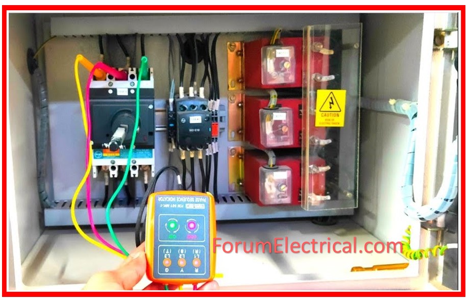
Check Transformer Polarity (Current/Voltage): This is a visual check to ensure that current & voltage transformers are set up and wired in conformity with the issued engineering drawings.
Grounding: Using a low voltage continuity tester, all grounding to equipment and others should be verified to ensure appropriate metal case grounding.
High Potential (Hi-Pot Test)
The High Potential (Hi-Pot) Test is an essential procedure for determining the insulation strength of low voltage (LV) electrical panels by providing a voltage much higher than the normal operating level.
This test detects insulation faults such as
- Leakage currents,
- Insufficient clearances, or
- Weak insulation,
which could result in device failure or electrical risks.
During the test, a high DC (or) AC voltage is supplied between the conductors and ground to measure the leakage current.
If the current continues within acceptable levels with no breakdowns, the insulation is considered dependable.
The Hi-Pot test assures that electrical panels are safe, reliable, and compliant with industry standards, making it a crucial component of quality assurance in the electrical systems.
Insulation Resistance (Megger) Test
Insulation tests determine the level of circuit resistance to the current leakage.
This test is run when resistance measurements are requested and specified.
The value of insulating resistance varies according to temperature, humidity, and the cleanliness of equipment and wiring.
It is also determined by the equipment’s kind, size, voltage rating, insulating materials used, building process, and previous insulation records.
Power Cable, Buses Insulation & Isolation Test
Insulation breakdown resistance must be tested on power cables and buses, both
- Phase to Phase &
- Phase to Ground.
If neutral is appropriate, it will be considered the fourth phase.
These tests are carried out under room temperature & up to 95% relative humidity at an altitude of less than 2000 meters, as specified for freshly constructed equipment.
Equipment under test must be de-energized.
The test voltage shall be (two times rated + 1000) for one minute, and the frequency of the test voltage shall be at least the rated frequency of equipment tested, with an essentially sinusoidal wave form.
- Low voltage devices,
- Semiconductors,
- Meters,
- Instrumentation,
- Transformers,
- Grounding circuits, and so on
must all be taken into consideration for the dielectric tests.
Acceptance Criteria
Electrical Clearance
Between live components with opposite polarity via air.
| 0 – 125 V AC | 125 – 250 VAC | 250 – 600 VAC |
| 1 / 2″ | 3 / 4 “ | 1 “ |
Insulation Resistance Test
All instrumentation & control fuses have been removed, and switching devices have been placed in the closed position.
| Test voltage DC | Acceptance IR(MΩ) |
| 500 V | 10 MΩ |
| 1000 V | 25 MΩ |
Torque Values for Electrical Joints
In low voltage MCC, the following are examples of bolts, screws, and nuts that are utilized.
| M6 | 5-10 N.M |
| M8 | 20 N.M |
| M10 | 40 N.M |
| M12 | 70 N.M |
Conclusion
In conclusion, FAT processes for Low Voltage MCC, SWBD, & SWGR panels ensure equipment quality and safety through extensive in-process and final inspections. Mechanical, continuity, insulation, and functional operation tests are performed according to quality requirements.
Manufacturers follow these procedures to keep equipment in top shape, lowering the risk of failure and assuring electrical system safety.
These thorough FAT procedures ensure customers that the panels meet design and operational criteria before deployment.


 uses inspections and tests to ensure that quality and safety criteria are achieved. It includes mechanical, continuity, functional, and insulation testing to ensure correct functioning, dependability, and conformance to NEMA and ANSI standards before installation.)