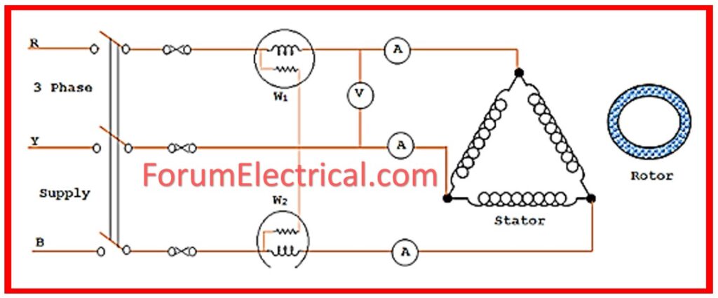
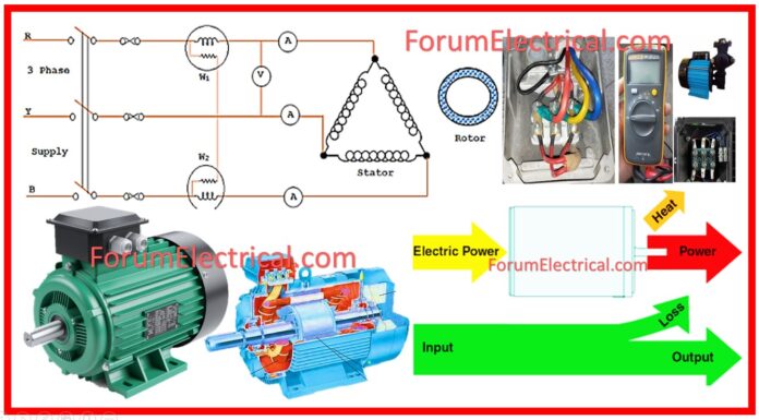
The Factory Acceptance Test, often known as the FAT, takes place on electrical equipment and is an essential phase in the process of procurement and deployment.
- FAT Test of Electric Motors
- 1). D.C. Resistance Test
- 2). Insulation Resistance Test
- 3). Locked-Rotor Current Test
- 4). Locked-Rotor Power Test
- 5). No Load Current Test
- 6). No Load Power Test
- 7). Vibration Test
- 8). Noise of No Load Test
- 9). Bearing Temperature Test
- 10). Voltage Withstand Test
- 11). Direction of Rotation Test
Before electrical equipment is sent to the location of the customer, it is subjected to testing and verification to ensure that it is of high quality, functional, and performance standards.
A number of significant functions are performed by the FAT test.
FAT Test of Electric Motors
The Factory Acceptance Testing (FAT) phase of the quality assurance process for electric motors is an essential step that serves a significant part in ensuring that the motors meet the design specifications and operating standards before they are deployed.
The performance of the motor, its durability, and its conformity to industry standards are all evaluated through these tests.
The Functional Acceptance Test (FAT) is comprised of a set of evaluations that are intended to imitate real-world operating conditions & identify any faults.
The following is a list of 11 essential tests that are commonly carried out during the FAT of electric motors:
1). D.C. Resistance Test
2). Insulation Resistance Test
3). Locked-Rotor Current Test
4). Locked-Rotor Power Test
5). No Load Current Test
6). No Load Power Test
7). Vibration Test
8). Noise of No Load Test
9). Bearing Temperature Test
10). Voltage Withstand Test
11). Direction of Rotation Test
1). D.C. Resistance Test
Ruv, Ruw, and Rvw are the parameters.
Method of Testing: Utilizing an ohmmeter (or) multimeter to determine the resistance that exists between every pair of phases that are contained within the motor windings.
Importance: The significance of this is that it provides information about the state of motor windings. It is possible that short circuits or flaws in the windings are the cause of resistance levels that are low or imbalanced.
Standard: The D.C. Resistance Test follows IEEE 118 (or) IEC 60034-1 standards to test motor winding resistance, ensure uniformity, and detect potential problems.

2). Insulation Resistance Test
Method of Testing: The megohmmeter, often known as a megger, is the instrument that is used to measure the insulation resistance. A high direct current voltage, normally between 500 and 1000 volts, is applied to the motor windings in order to carry out this test. The resistance between motor windings & motor casing (ground) is then measured.
Importance: It is important to note that a high insulation resistance implies that the insulation quality is high, which helps to prevent leakage currents and ensures safety. Deterioration of the insulation, as well as moisture or contamination, can be indicated by lower readings.
Standard: Using a megohmmeter, evaluate the insulation quality of motor windings to ensure safe operation under specified voltage circumstances, as per IEEE 43 or IEC 60034-27-1 standards.
3). Locked-Rotor Current Test
Method of Testing: The method of testing involves starting the motor with its rotor locked (kept stationary), and then measuring the starting current with either an ammeter or a power analyzer.
Importance: It is important to note that locked-rotor current refers to the maximum current that is drawn by the motor when it is powered on but is not permitted to rotate. It is essential for determining the ideal size of motor protection and comprehending the behavior of the motor during starting.
Standard: The Locked-Rotor Current Test, governed by IEEE 112 or IEC 60034-2-1, monitors the current drawn when rotor is locked to verify starting current ratings.
4). Locked-Rotor Power Test
Method of Testing: The method of testing involves taking measurements when the motor is in a locked-rotor condition. A power meter is used to determine the amount of power that is drawn down during the test.
Importance: Locked-rotor power is a measure of the amount of energy that the motor consumes when it is starting up under full load. This has an impact on both the motor’s efficiency and its performance during the startup process.
Standard: The Locked-Rotor Power Test, in accordance with IEEE 112 or IEC 60034-2-1, measures power input under locked-rotor conditions to ensure torque and power stability.

5). No Load Current Test
Method of Testing: An ammeter is used to measure the current that is drawn by the motor as it is operating at its rated voltage and there is no load on it.
Importance: It is important to note that the no-load current demonstrates how efficient the motor is when it is operating without a load. A higher current in the absence of load may be an indication of problems such as mechanical friction (or) electrical losses.
Standard: The No-Load Current Test (per IEEE 112 or IEC 60034-2-1) assesses the motor’s current draw at no load to ensure it fulfills design parameters without excessive losses.
6). No Load Power Test
Method of Testing: The method of testing involves using a power meter to determine the amount of power that is consumed by motor as it is operating without any load.
Importance: An understanding of the inherent losses of motor, such as friction, windage, & core losses, can be gained from measuring the power output of the motor when it is not under load.
Standard: The No-Load Power Test (IEEE 112 or IEC 60034-2-1) evaluates efficiency and performance by measuring power consumption during no-load conditions.
7). Vibration Test
Method of Testing: Vibration analysis is frequently carried out with the use of a vibration meter (or) accelerometer, with vibrations being measured in millimeters per second.
Importance: Maintaining low vibration levels inside the motor is essential for ensuring its longevity and maintaining its optimal functioning. When vibration is excessive, it may be an indication of a mechanical imbalance, misalignment, (or) bearing problems.
Standard: In accordance with ISO 10816-3 or IEC 60034-14, this test ensures the motor functions at permissible vibration levels, preventing mechanical failure.
8). Noise of No Load Test
Method of Testing: A sound level meter is positioned in close proximity to the motor in order to measure the levels of noise.
Importance: Noise might be an indication of mechanical wear, poor alignment, or problems with the bearings. This is some factor that has to be considered. In order to ensure that the motor functions within the industry’s guidelines for noise pollution, acceptable noise levels must be maintained.
Standard: The Noise of No-Load Test (ISO 3744 or IEC 60034-9) monitors sound pressure levels during no-load operation to ensure compliance with noise requirements.
9). Bearing Temperature Test
Method of Testing: In order to determine the temperature of the bearing while the motor is operating, a temperature sensor, which can be a thermocouple (or) an infrared thermometer, is utilized.
Importance: Bearings should ensure that they are operating within the temperature limitations that have been stipulated in order to avoid damage. Temperatures that are much higher than normal are an indication of lubrication issues or bearing friction.
Standard: The Bearing Temperature Test follows ISO 13709 or IEC 60034-1 standards and monitors bearing temperature during operation to prevent exceeding thermal limits.

10). Voltage Withstand Test
Method of Testing: In order to evaluate the motor’s insulation strength, a high voltage, typically alternating current (AC), is applied across the motor windings & the frame for a period of sixty seconds.
Importance: The purpose of this test is to check that the insulation of the motor is capable of withstanding the high operating voltages without breaking down. If this test is not passed, it may result in electrical failures while the system is being operated.
Standard: The Voltage Withstand Test (IEC 60034-1 or IEEE 95) tests the dielectric strength of motor windings by applying high voltage.
11). Direction of Rotation Test
Method of Testing: The method of testing involves turning on the motor and visually inspecting it to determine the direction in which it is rotating.
Importance: Due to the significance of its application, it is absolutely necessary to rotate the motor in the appropriate direction. While some motors have been developed to rotate in the both directions, others are only meant to revolve in one direction as their primary function.
Standard: Conducted in accordance with IEC 60034-1, this test confirms the proper direction of rotation for design & connection requirements.
Each of these tests is necessary to ensure that the motor satisfies the specified specifications and performs reliably in its intended application. FAT provides that end users receive high-quality & reliable electric motors that are ready for installation and service.


