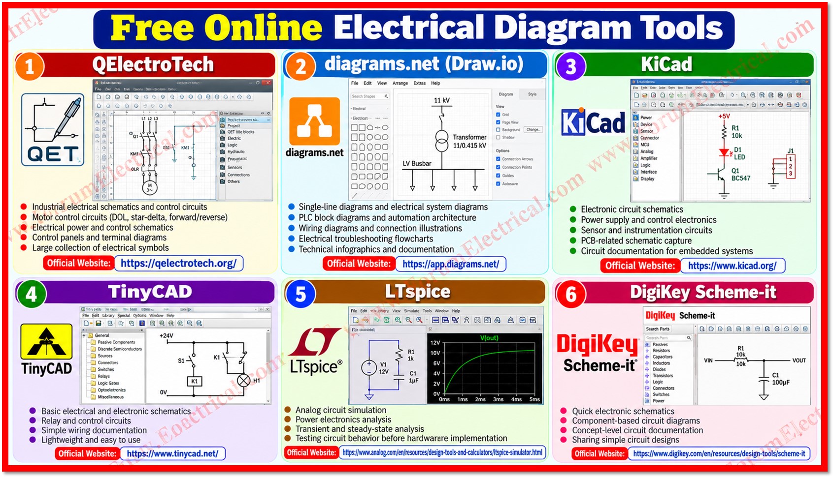
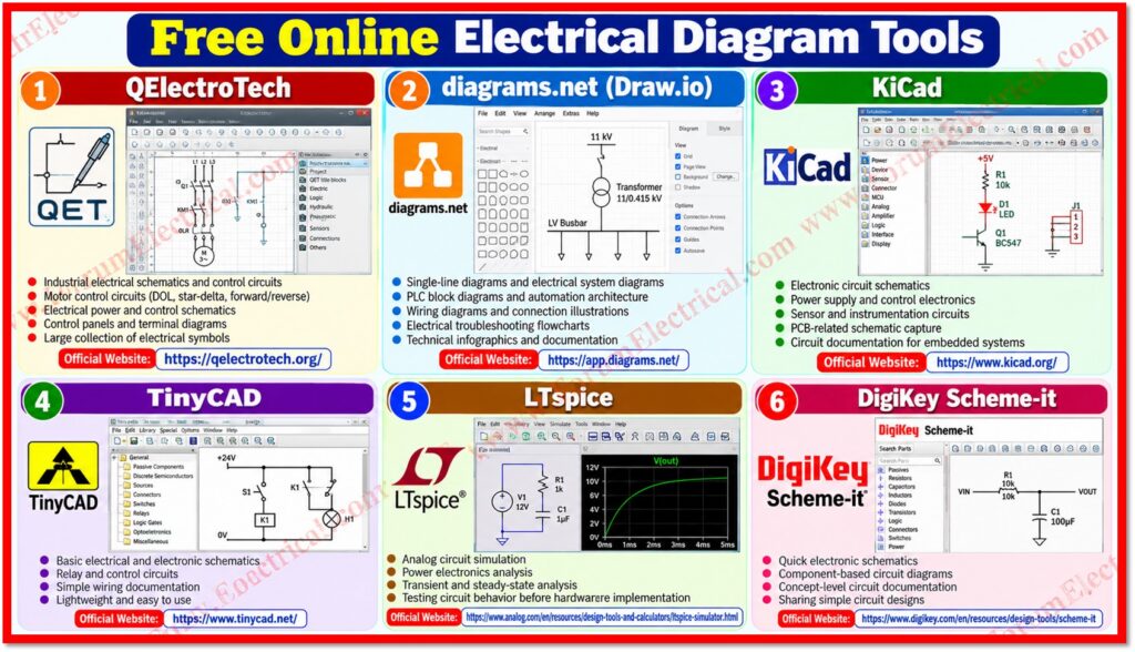
Electrical engineers, technicians, designers and technical content creators regularly require to prepare clear and technically accurate electrical diagrams.
These may include
- Single-line diagrams (SLDs),
- Control wiring diagrams,
- Motor control circuits,
- PLC schematics,
- Panel layouts,
- Transformer connections,
- Protection circuits and electronic schematics.
Professional electrical CAD packages can be expensive but several free and open source tools can handle a wide range of drawing requirements.
This post presents practical free (or) freely accessible tools for creating electrical diagrams and explains their main applications, strengths and limitations.
The tools are particularly useful for industrial electrical documentation, training material, engineering articles and basic design work.
Top Free Electrical Diagram Tools
| Tool | Best Application | Availability | Official Link |
| QElectroTech | Industrial electrical schematics and control circuits | Free / Open Source | Official Website |
| diagrams.net | SLDs, block diagrams, wiring diagrams and flowcharts | Free | Official Website |
| KiCad | Electronic schematics and PCB design | Free / Open Source | Official Website |
| TinyCAD | Basic electrical and electronic schematics | Free / Open Source | Official Website |
| LTspice | Circuit schematics and electrical simulation | Free | Official Website |
| DigiKey Scheme-it | Online electronic and circuit diagrams | Free | Official Website |
1). QElectroTech
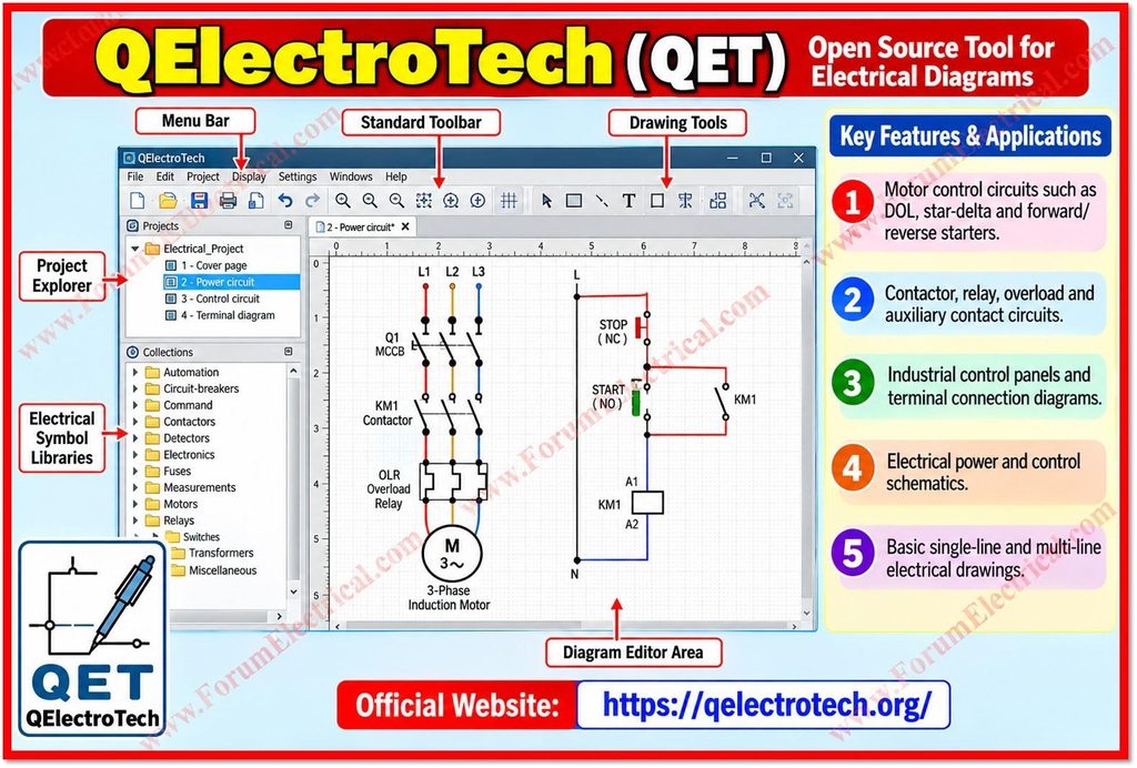
QElectroTech is an open-source application designed specifically for creating electrical diagrams.
It is particularly suitable for industrial electrical documentation as it provides a large collection of electrical symbols and supports structured schematic creation.
- Motor control circuits such as DOL, star-delta and forward/reverse starters.
- Contactor, relay, overload and auxiliary contact circuits.
- Industrial control panels and terminal connection diagrams.
- Electrical power and control schematics.
- Basic single-line and multi-line electrical drawings.
Official website: QElectroTech
2). diagrams.net (Draw.io)
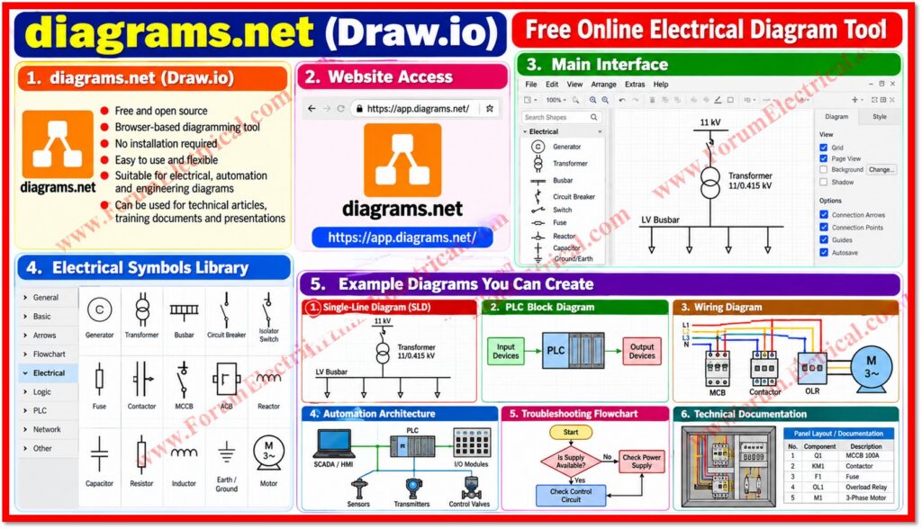
diagrams.net is a browser based diagramming platform that is useful when a fast and flexible drawing tool is needed.
It can be used without installing a dedicated electrical CAD package and is convenient for technical articles, training documents & engineering flow diagrams.
- Single-line diagrams and simplified electrical system diagrams.
- PLC block diagrams and automation architecture.
- Electrical troubleshooting flowcharts.
- Wiring & connection illustrations.
- Technical infographics & documentation.
Official website: diagrams.net (Draw.io)
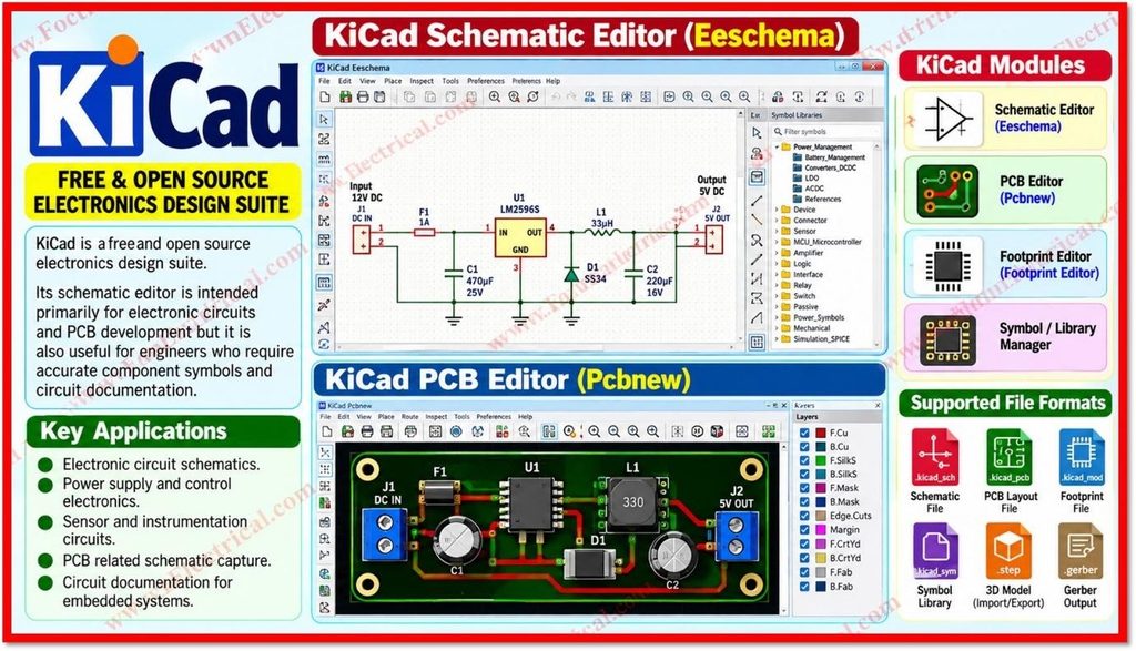
3). KiCad
KiCad is a free and open source electronics design suite.
Its schematic editor is intended primarily for electronic circuits and PCB development but it is also useful for engineers who require accurate component symbols and circuit documentation.
- Electronic circuit schematics.
- Power supply and control electronics.
- Sensor and instrumentation circuits.
- Circuit documentation for embedded systems.
Official website: kicad
4). TinyCAD
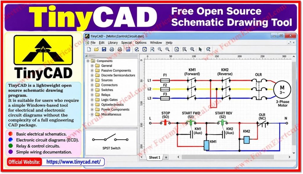
TinyCAD is a lightweight open source schematic drawing program.
It is suitable for users who require a simple Windows-based tool for electrical and electronic circuit diagrams without the complexity of a full engineering CAD package.
- Basic electrical schematics.
- Electronic circuit diagrams (ECD).
- Relay & control circuits.
- Simple wiring documentation.
Official website: TinyCAD
5). LTspice
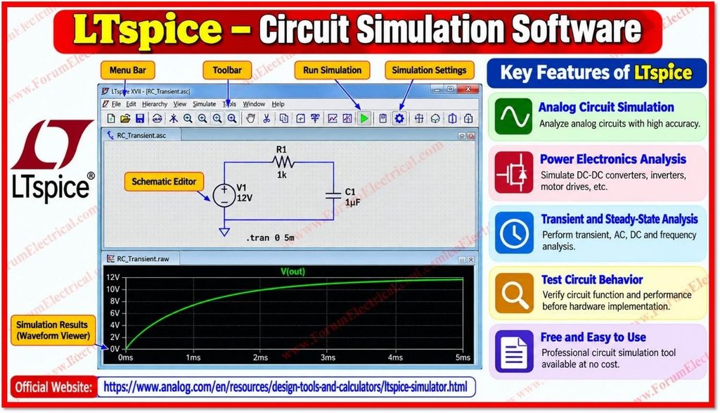
LTspice is a free circuit simulation program that combines schematic capture with electrical simulation.
It is especially useful when the engineer requires to verify circuit performance rather than only draw the circuit.
- Analog circuit simulation.
- Power electronics analysis.
- Transient and steady-state analysis.
- Testing circuit function before hardware implementation.
Official website: LTspice
6). DigiKey Scheme-it
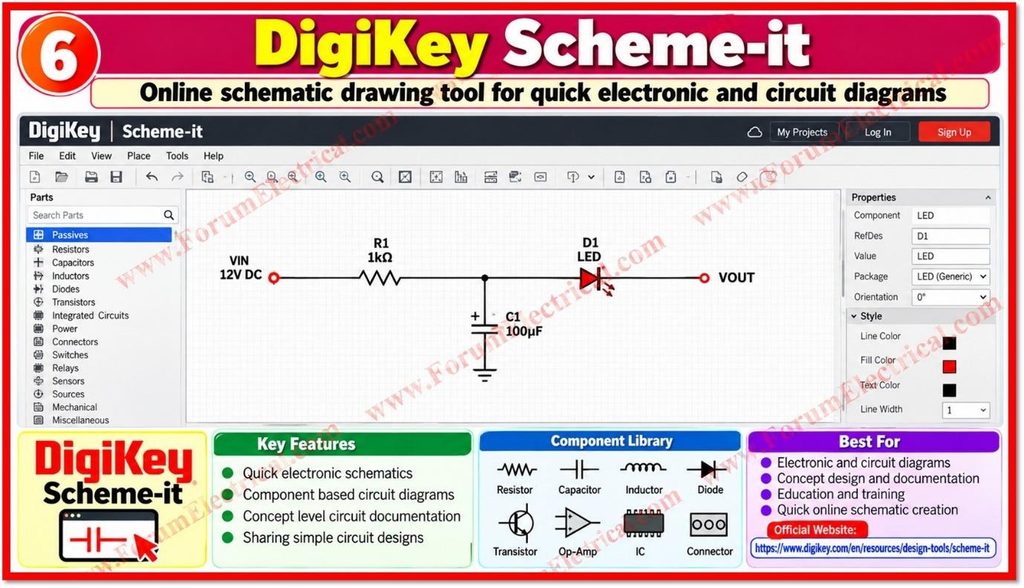
Scheme-it is an online schematic drawing tool that can be utilized to create electronic & circuit diagrams directly in a web browser.
It is useful for quick documentation when a desktop CAD application is not required.
- Quick electronic schematics.
- Component based circuit diagrams.
- Concept level circuit documentation.
- Sharing simple circuit designs.
Official website: DigiKey Scheme-it
How to select the Right Tool?
The most suitable software depends on the type of drawing that is required, symbol library, need for simulation, collaboration requirements and the level of engineering detail.
| Requirement | Suitable Tool |
| Industrial electrical control circuits | QElectroTech |
| Quick online diagrams and technical graphics | diagrams.net |
| Electronic circuits and PCB related schematics | KiCad |
| Simple Windows schematic drawings | TinyCAD |
| Circuit analysis and simulation | LTspice |
| Fast browser based circuit documentation | DigiKey Scheme-it |
Important Engineering Considerations
- Use recognized IEC, ANSI (or) other applicable symbol conventions for the intended project.
- Verify conductor numbering, terminal numbers, contact designations and cross references before publishing a drawing.
- Clearly identify voltage levels, protective devices, control devices & equipment ratings where applicable.
- Do not treat a diagramming tool as a substitute for engineering calculations, protection coordination (or) design verification.
- For installation and commissioning work, drawings must be checked against the approved project drawings and applicable standards.
- For public technical content, verify all connections and symbols before publication because a visually attractive diagram may still contain a technical error.
Electrical Drawing Workflow
- Define the purpose of the diagram and the intended audience.
- Prepare the electrical sequence (or) functional logic before use for drawing.
- Select the correct symbols & establish a consistent drawing convention.
- Create the power circuit first followed by the control (or) signal circuit.
- Check every connection against the original circuit (or) engineering design.
- Export the final drawing at a suitable resolution for web, PDF (or) print publication.
- Perform a final technical review before publishing.
Conclusion
Free electrical diagram software can provide a practical alternative to expensive electrical CAD packages for many documentation and learning requirements.
QElectroTech is particularly useful for industrial electrical schematics while diagrams.net is convenient for fast online diagrams and technical graphics.
KiCad and LTspice are better suited to electronic design and circuit analysis.
Selecting the online tool according to the required drawing type utilized to improve productivity while maintaining clear & consistent documentation.

