What are Single Line Diagrams (SLD) and how are they used?
An electrical system is shown effectively in a single-line diagram, commonly referred to as an SLD (or) one-line diagram. The nodes & connections in the system are represented by symbols and lines, and electrical properties may also be shown.
A single-line diagram of the power distribution system in a data centre is used to enhance planning and troubleshooting, provide redundancy, and lessen possible outages.

Single-line diagrams employ power system node symbols.
SLD, or one-line diagram, is the abbreviation for an electrical single line diagram. It is a simplified representation of the whole system or a section of power system that displays where all of the significant components of equipment are electrically located.
A 3-phase power system may be more simply explained using a single line diagram.
To provide the engineer (or) a system operator with a complete understanding of the electrical system, the necessary information is provided. It also contains the measures for system protection.
Importance of Single Line Diagram
- An accurate single-line diagram of the electrical power distribution system for a commercial or industrial facility is a tool that is of immeasurable value. It’s a one-line diagram.
- Single-line diagrams show an electric circuit’s path and components using conventional symbols and lines.
- IEEE Std 315-1975 defines single-line diagram symbols. The single-line figures show electricity flow across the distribution system.
- The single-line illustration shows where electricity enters the system and where it should be unplugged to clean or isolate a section.
- Operating diagrams guide industrial and commercial power system maintenance. Power system diagrams are the primary tool.
- Operating and maintaining an industrial (or) commercial complex without these system diagrams would be difficult and dangerous.
- A full single-line diagram and installation plan should provide enough data to design and assess the electric power system.
- Single-line diagrams is for system-protection design & fault-current analysis.
Features of Single Line Diagram
The following features should help in ensuring accuracy and simplicity of interpretation:
a) Keep things simple
A basic single-line diagram should be composed of short, straight lines & components, similar to how a block diagram is constructed. The overall image of the electrical system should be reasonably simple to get. The system should be maintained to one sheet as much as feasible. If the system is big enough that more than one sheet is required, the split should be formed at voltage levels or distribution centres.
b) Preserve relative geographic connections
A single-line diagram form may be superimposed over the facility layout design. This is very useful for quickly determining the location of the system’s primary components for operational needs. However, understanding the overall system functioning from this representation may be more difficult. A graphic like this might be used for very basic systems. However, for more complicated systems, it should be used in combination to the basic single-line diagram.
c) When creating the single-line diagram, keep the approximate relative locations of the components in reference
The graphic should be as basic as feasible and set out in the same way that an operator would see the equipment. The diagram does not have to be complex in order to demonstrate geographical linkages.
NOTE: In addition to the single-line diagram, a site plan with device positions may be necessary.
d) Try to avoid duplication
Every sign, & letter has a specific meaning. The reader should be capable to comprehend each one without difficulty. In this respect, before publishing the publication, equipment names should be chosen; these names should then be utilised consistently.
Important Single Line Diagram Symbols
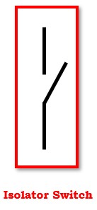
1). Isolating switch
In electricity substations, a portion of the system must be disconnected for general maintenance & repairs. An isolating switch or isolator is used to do this. An isolator is basically a switch that opens a circuit when there is no load. Assume that the whole substation is split into five portions. For maintenance, each part may be separated using an isolator.
2). Busbar
A busbar is a grouping of bus conductors with connecting connections and insulating supports. It is a grounded metal enclosure that contains factory-mounted, bar (or) insulated conductors, which are often copper or aluminium bars, rods, or tubes.

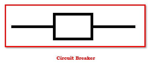
3). Circuit breaker
A circuit breaker is a component of a circuit that may open or shut a circuit under normal & fault situations. It is configured to function manually under normal circumstances and automatically during fault situations. It is a sort of switching device that may be safely used under high current carrying situations. It is utilised to safeguard and regulate the power system by promptly disconnecting and reconnecting various sections of the power system.
4). Transformers
Transformers play an important role in electricity transmission and distribution. They are used to increase or decrease voltage. A step-up transformer is often used in a power plant to boost the produced voltage to a greater value. A step-down transformer is utilised at succeeding substations to lower the supply voltage & then deliver it at the utilisation end.
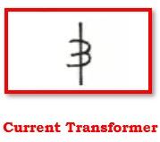
A current transformer is a step-up (or) step-down transformer that multiplies current by a predetermined ratio. For example, if a current transformer has a rating of 100/5A, the main current is 100A and the secondary current is 5A. It is an instrument transformer. The voltage transformer (or) potential transformer is another kind of instrument transformer.
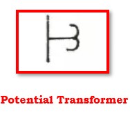
A potential transformer is a type of instrument transformer that is used for protection & measurement. In a power system, it measures the high alternating voltage. It is often a step-down transformer with fewer windings on the secondary side.
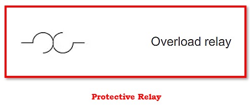
5). Protective Relays
The basic objective of protective relays in substations is to remove any element from operation as soon as it experiences a short circuit. It also safeguards when a component of a system begins to act abnormally, which may cause harm (or) interfere with the proper operation of the whole system. Protection relays are classified according to their properties, logic, actuation parameters, and operating method.
Advantages of the Single Line Diagram
- Provides a general knowledge of the system & facilitates evaluation.
- It speeds up and streamlines the troubleshooting procedure.
- It improves employee safety & makes maintenance easier.
- It assures the system’s safety and dependability.
Applications of Single Line Diagram
Power distribution in an establishment is shown using a single-line diagram. As equipment at the facility gets added, altered, or withdrawn, the diagram should be maintained correct and up to date.
A single-line diagram has the following advantages when used in a data centre:
- Get acquainted with the architecture and design of the power distribution system
- To enhance system dependability, record redundant power transmits
- Planning and problem-solving are made easier, and maintenance tasks are made more productive.
- Ensuring observance of norms and rules.
- Keeping activities safe for personnel protection.
- They are quite helpful in organising maintenance operations.
- Helps in the rerouting of electricity complying with a malfunction.
- Useful for changing system setups by altering orders.
- It allows to see the connections between smaller areas of the power system & the larger system.


