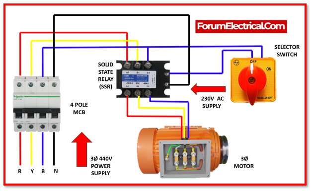
In this post, let’s take a look at the wiring schematic and connection diagram for a 3-phase motor, SSR, & selector switch to turn ON & OFF the motor by controlling the selector switch.
To regulate the motor, we have utilized SSR rather than a magnetic contactor (or) electromechanical relay. SSR has several benefits, which is the reason for utilization in motor control.
A Contactor might be used preference instead of an SSR for additional controlling possibilities and complex control circuits.
However, as per needs merely require ON/OFF operation, an SSR is a useful option.
SSRs are employed with motors because they have various benefits over conventional magnetic contactors & electromechanical relays.
What is Solid State Relay (SSR)?
A Solid-State Relay (SSR) is an electrical switching device that turns ON (or) OFF when a power source (AC or DC) is applied all over its control terminals.
SSR can turn on and off extremely fast, which is useful in motor control operations that demand accurate switching time.
This may assist to enhance the motor controlling system’s overall efficiency and performance.
SSRs also have no mechanical moving components, unlike magnetic contactors (or) electromechanical relays.
Because there is no operational failure (or) damage from mechanical switching, they are more dependable & have a longer lifetime.
Circuit Diagram
The connection among a 3-phase motor, an SSR, & a Selector switch can be seen below:
Components
- A four-pole MCB
- A three-phase SSR with a 230V AC power source.
- A standard ON/OFF Selector Switch
Wiring Methodology
- The 4-Pole MCB serves as the primary incoming switch. As a result, the input power supply is linked to the MCB’s input.
- All three phases from the MCB output are connected to the SSR’s three-phase input terminals (A1, B1, C1).
- The motor’s three-phase input terminals are linked to the SSR’s output terminals (A2, B2, C2).
- The neutral connection from the MCB output is linked directly to neutral terminal of the SSR.
- In series with the selector switch, any phase terminal (here B phase) is linked to the phase terminal of the SSR.
Operating Procedure
- Initially, the MCB needs to be initiated.
- When want to operate the motor, must turn on the selection switch.
- The motor will be shut off if leave the switch in the OFF position.
Function using SSR
SSR’s include a low-voltage control input (230V AC in this case) that is utilized to activate (or) deactivate the solid-state relay. As a result, while the switch is kept in the ON position, the 230V AC control input voltage gets applied, triggering the semiconductor switch inside the SSR. So, the SSR was switched on, and electricity proceeded to flow from the input terminal to the output terminal, and the motor start working.
When the switch is turned OFF, the control input voltage generated by the SSR is withdrawn or falls below a particular threshold, causing the semiconductor switch in SSR to turn off and the power supply to the load (here, the motor) to be shut off.
Advantages
- Reliable and efficient,
- This series is a suitable selection for industrial motors.
- Each device has overvoltage protection & IP20 touch safe casing.
Precautions for Safety
- Before working on any of the electrical connections, take the necessary security measures.
- Disconnect the motor’s power source and observe all safety precautions, including wearing adequate personal protective equipment (PPE).
- Refer to the manufacturer’s requirements and guidance for choosing the appropriate SSR relay, MCB, and motor rating.
- To establish the proper protective measures for the unique application, consult the manufacturer’s recommendations, a professional electrician, or an electrical engineer.
Summary
Using an SSR relay to control a three-phase motor has various benefits, including quick switching, increased dependability, and decreased wear and tear. It is possible to effectively install an SSR relay for reliable and accurate control of three-phase motors by following the step-by-step method given in this post. Always follow safety precautions and reference the manufacturer’s requirements and directions for the individual SSR relay type being utilized.


