
An instrument transformer in an alternating current system measures electrical quantities such as voltage, current, power, power factor, energy, and frequency.
Instrument transformers are also used in conjunction with protection relays to safeguard power systems.
An instrument transformer’s primary function is to reduce the voltage and current of an alternating current system. Because the power system’s voltage and current levels are too high, designing measuring instruments to measure such high-level voltage and current is difficult and expensive.
The measuring instruments are typically designed for 5A and 110V.
With the help of an instrument transformer, it is possible to measure large electrical quantities with measuring instruments. Because these instrument transformers are used in modern power systems.
Types of Instrument Transformers:
Instrument transformers are of two types
- Current transformers
- Potential Transformers
Symbols of Current & Potential Transformer:
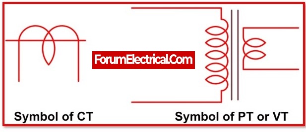
Current Transformer (CT):
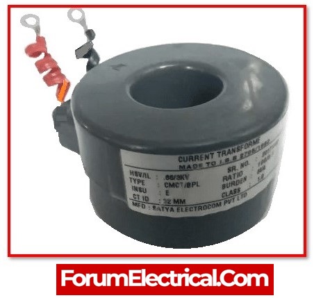
The current transformer reduces the power system’s current to a low enough level that it can be measured with a small-rated ammeter (i.e. a 5A ammeter). The diagram below depicts a typical current transformer connection.
There are only a few turns in the CT primary. The primary is connected in series to the power circuit. As a result, it is also known as a series transformer. The secondary winding has many turns and is directly connected to an ammeter. Because the ammeter has a very low resistance, the secondary of the current transformer was almost short-circuited.
One secondary terminal is grounded to prevent high voltages on the secondary. As a result, the chances of insulation breakdown are reduced, and personnel are protected from high voltage. In addition, before disconnecting the ammeter, a switch “S” short-circuits the secondary to prevent high voltage build-up.
Types of Current Transformers (CTs):
- Wound-type
- Bar type
- Toroidal
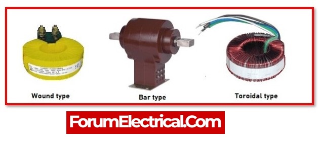
1. Wound-type CT:
A current transformer (CT primary) is directly connected in series to the load whose current is to be measured. The primary and secondary cannot be separated in this case. The best example is a switchyard high voltage current transformer.
2. Bar type CT:
They are typically constructed with a copper or aluminium bus bar encircled by a secondary winding over ferromagnetic cores. The bus bar serves as a primary winding with a single turn. They are directly connected to current carrying conductors. They are also known as bar-primary current transformers.
3. Toroidal CT:
They contain no primary winding. Toroidal CTs have a window or hole through which a line transports current flowing through the network. The CT’s secondary is portable. A CT of the digital Tong tester is of the toroidal type.
Potential Transformer (PT) or Voltage Transformer (VT):
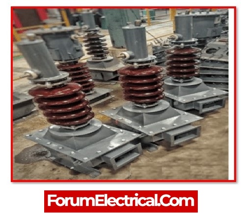
A voltage transformer is another name for a potential transformer. It is an instrument transformer that converts voltage from one value to another. It is used to reduce the voltage of the power system to a lower level that can be measured with a small rated voltmeter. i.e. 110V or 120V.
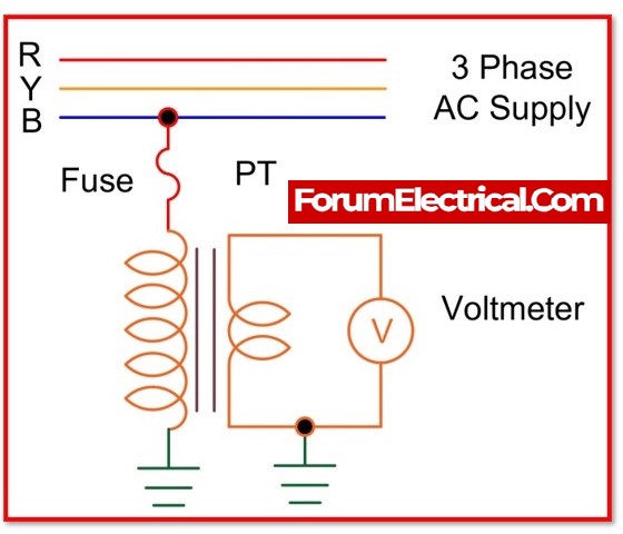
The PT or VT is built in the same way as any other transformer. This reduces the voltage to a safe level, which can be easily measured with a voltmeter or other low-voltage device.
Because it is a step-down transformer, the number of turns in the primary winding is greater than the number of turns in the secondary winding. A potential transformer connects across or parallel to the line to record ratio or angle errors.
A potential transformer is used to measure single-phase switching voltages as well as three-phase terminals.
A potential transformer is a type of transformer that can be used to take readings from electrical service connections. For accurate power and energy measurement, the PT or VT is designed with lower ratio and phase angle errors.
Types of Potential Transformers (PTs):
Based on their function, they are three types.
- Electromagnetic
- Capacitor
- Protection
1. Electromagnetic Transformer:
Primary and secondary windings are wound on a magnetic centre in the same way that the main transformer is. It operates at voltages greater than or less than 130 kV. The primary section is determined by phase, while the secondary section is determined by ground. These components are found in relays, measurements, and high voltage networks.
2. Capacitive Voltage Transformer:
A series of capacitors connects the main or secondary windings. The capacitor lowers the voltage by acting as a potential divider. This device detects the voltage emitted by the secondary winding. It’s also used in power line communications. It is the most costly.
3. Protection (Voltage Transformer):
It can be single-phase or tri-phase and operates with extreme precision. It is used to perform and monitor instrument, relay, and other device measurement tasks.
The number of instruments in the relay connected to the secondary power transformer increases the number of errors. As a result, the devices must be connected to the transformer’s secondary in proportion to the transformer’s total VA.
Power Metering using CT and PT:
The CT and PT instrument transformers are used to measure power in the circuit. The power measurement circuit’s circuit diagram is shown in the figure below. The CT is connected to the load in series, and the PT is connected to the supply system in parallel.
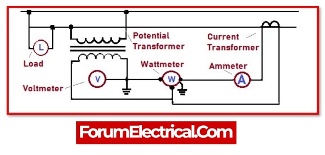
Current transformers (CT) and potential transformers (PT) are used in tandem to measure power from a utility to a customer. Wattage (W) or power (P) is calculated by multiplying current by voltage.
A potential transformer is used to measure voltages, whereas a current transformer is used to measure current. The wattmeter is linked in series with the ammeter and must be powered by 5A or less.
