What is Insulation Coordination?
Insulation Coordination is the procedure of determining the appropriate insulation levels and configurations of various power system components.
- What is Insulation Coordination?
- Why is Insulation Coordination needed?
- Insulation Coordination – Common Terminology
- 1). Basic Impulse Insulation Level (BIL)
- 2). Withstand Voltage
- 3). Chopped Wave Insulation Level
- 4). Critical Flashover Voltage
- 5). Impulse Ratio
- Insulation Coordination – Overvoltage Consideration
- 1). Internal Overvoltages
- 2). Switching Surges
- 3). External Overvoltages
- Insulation Coordination Standards
- Overvoltage Surge Protection
- 1). Rod/Spark Gaps
- 2). Surge Arresters
- Selection Procedure for Surge Arresters
- Common Ratings for Surge Arresters
It is the selection of an insulation design that will survive the voltage stresses that the system (or) equipment shall be subjected to, in conjunction with the appropriate surge arrester.
The procedure is based on the known properties of voltage surges & surge arresters.
Why is Insulation Coordination needed?
Insulation coordination will be utilized in determining an ideal insulation level and the necessary protective mechanisms to ensure the system’s safe functioning under adverse voltage situations.
Insulation coordination is now an essential requirement for electrical systems in order to verify conformity with IEC / IEEE standards and the corresponding Electricity Transmission Codes.
The specifications outlined in the IEC / IEEE standards must be followed in order to meet the design parameters indicated; however, due to geographical conditions, it is recommended to conduct insulation coordination to ensure an exact design parameter that is appropriate for the respective network/plant.
Insulation Coordination – Common Terminology
Some common terminology that should be understood when doing an Insulation Coordination Study.
- Basic Impulse Insulation Level (BIL)
- Withstand Voltage
- Chopped Wave Insulation Level
- Critical Flashover Voltage
- Impulse Ratio
1). Basic Impulse Insulation Level (BIL)
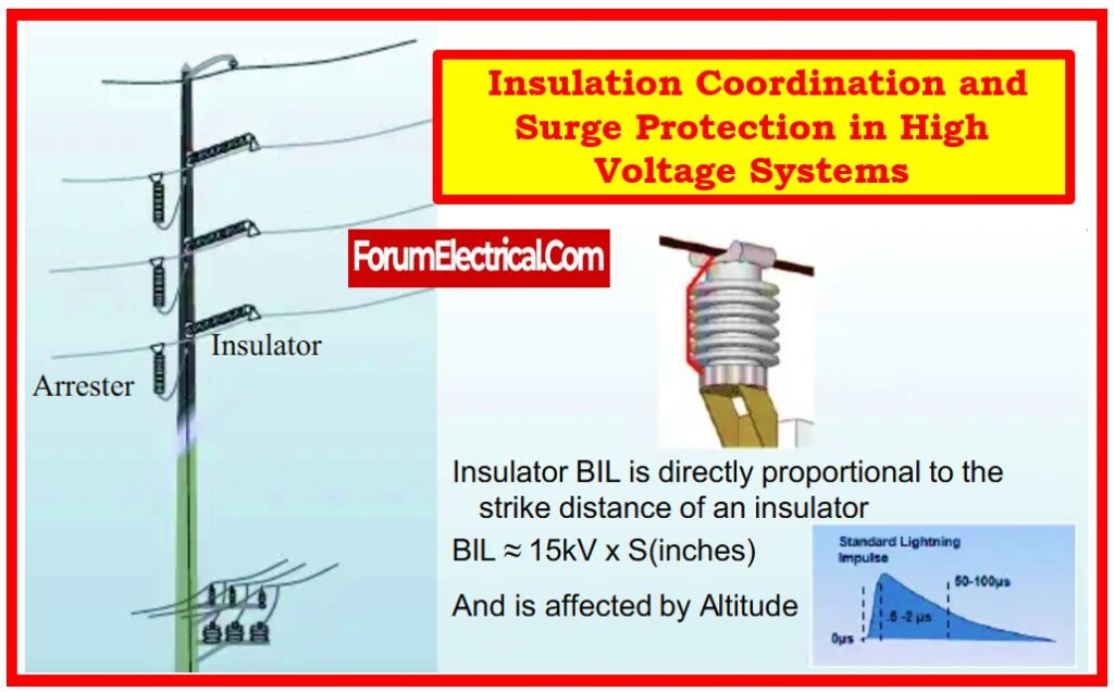
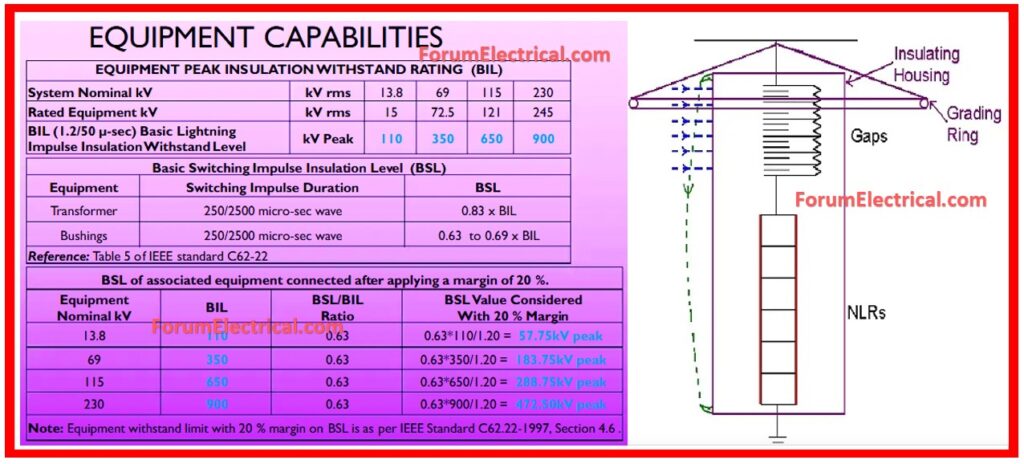
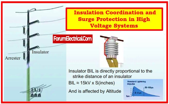
The reference insulation level is defined as an impulse crest (or peak) voltage with the standard wave of no more than 1.2 x 50 microseconds.
A 1.2 x 50 microsecond wave indicates that the impulse takes 1.2 microseconds to reach its peak before decaying to 50% of that peak in 50 microseconds.

2). Withstand Voltage
The BIL level that can be applied repeatedly to equipment without causing flashover, disruptive charge, or electrical failure during testing.
3). Chopped Wave Insulation Level
Determined by employing impulse waves with the same shape as the BIL waveform, but chopped after 3 microseconds.
In general, the Chopped Wave Level is expected to be 1.15 times the BIL level for oil-filled equipment which includes transformers.
Although for dry type equipment, it is considered that the Chopped Wave Level equals the BIL Level.
4). Critical Flashover Voltage
The peak voltage with a 50% chance of flashover (or) disruptive charge.
5). Impulse Ratio
Used for flashovers or insulation punctures.
The ratio of the impulse peak voltage to the 60 Hz voltage is what produces flashover or puncture.
Alternatively, it is the breakdown voltage at the surge frequency divided by the breakdown voltage at regular system frequency (60 Hz).
Insulation Coordination – Overvoltage Consideration
Considerations for an Insulation Coordination Study, including overvoltages.
There are three types of overvoltages that can occur in a plant:
- Internal Overvoltages
- Switching Surges
- External Overvoltages
1). Internal Overvoltages
Typically, these are brief power frequency overvoltages (or) weakly damped oscillatory voltages. The primary causes for those overvoltages include:
There are three types of phase-to-earth faults: single, double, and triple.
- Load Rejection.
- Ferro Resonance.
- Ferranti Effect.
2). Switching Surges
These surges are short in duration, erratic (or impulse-like), and heavily dampened. When the transmission voltage exceeds 300kV, the consequences of such overvoltages are extremely serious.
However, below 300 kV, some sources of these overvoltages include:
- Resonance occurs while switching transformer feeders, wires, or overhead lines.
- Ferro resonance occurs on transformer feeder double circuits when one circuit is turned off but the other parallel feeder remains active.
- Energizing a line can result in switching spikes, particularly at the remote end.
3). External Overvoltages
Lightning-induced overvoltages in power systems operating below 145kV are of more significance than the previously mentioned two categories of overvoltages. Lightning
Discharges are often relatively brief, unidirectional, and shaped similarly to the BIL waveform.
The point of insulation flashover is dependent on
- Location of the lightning strike.
- The magnitude of stroke.
- Rise time of the voltage wave.
- System insulation levels.
- System Electrical Characteristics.
- Local atmospheric or environmental circumstances.
Insulation Coordination Standards
The IEC – International Electrotechnical Commission & IEEE – Institute of Electrical and Electronics Engineers recommendations, as well as those of the CIGRE – Conseil International des Grands Réseaux Electriques, are widely used.
In India, the Bureau of Indian Standards (IS) approved the IEC standards (listed below) on the proposal of the High-Voltage Engineering Sectional Committee & with the agreement of the Electrotechnical Division Council.
- IS/IEC 60071-1:2019, Part 1: Definitions, Principles, and Rules.
- IS/IEC 60071-2:2023 Part 2: Application Standards.
- IS/IEC TR 60071–4:2004 Part 4: A computational reference to insulation coordination and electrical network modelling.
- IEC 60071-11:2022 Part 11: Definitions, Principles, & Rules for HVDC Systems.
- IEC 60071-12:2022 Part 12: Application Standards for LCC HVDC Converter Stations
- IEEE 82.1-2010: IEEE Standard for Insulation Coordination—Definition, Principles, and Rules
- IEEE 82.2-2022: IEEE Guidelines for the Application of Insulation Coordination.
Overvoltage Surge Protection
Overvoltage surge protection can be achieved using two methods:
- Rod/Spark Gaps
- Surge Arresters.
1). Rod/Spark Gaps
These devices are simple and inexpensive to install, and they are typically connected in parallel with insulators in between the live equipment terminal & ground.
Some drawbacks of these equipment are:
- When operating, they can generate a short circuit, requiring protection and isolating the device.
- Transformer inter-turn insulation experiences high stresses during operation.
- Plant insulation breakdown varies with overvoltage duration.
- At lower voltages, short distance gaps may cause malfunction due to debris deposited on terminals.
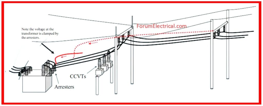
2). Surge Arresters
Latest surge arresters are of gapless Zinc Oxide variety.
Previously, silicon carbide arresters were utilized, but they have been replaced by ZnO arresters, that have a non-linear resistance characteristics.
Thus, it is feasible to eliminate the series gaps across the individual ZnO blocks that comprise the arrester.
Selection Procedure for Surge Arresters

Determine continuous arrester voltage. This is typically the system rated voltage.
Choose the rated voltage for arrester.
Identify the usual lightning discharge current. Below 36kV, 5kA rated arresters are used. Otherwise, a 10-kA arrester is utilized.
Determine the required long-term discharge capability.
For rated voltages below 36kV, a light duty surge arrester can be specified.
Heavy duty arresters can be chosen with rated voltages ranging from 36kV to 245kV.
Long duration discharge capability may be specified when the rated voltage exceeds 245kV.
Match the maximum fault current & protection tripping timings at the surge arrester location with its responsibility.
Choose a surge arrester with the appropriate porcelain creepage distance for the environmental circumstances.
Ensure surge arrester protection level meets standard IEC 99 guidelines.
Common Ratings for Surge Arresters

Rated Voltage: The arrester’s power frequency voltage should not exceed its rated voltage. Otherwise, it may fail to seal and absorb surge energy. For a properly earthed system: Maximum phase to the earth voltage equals 80% of maximum line voltage.
Rated Current: Arresters are evaluated using 8-20 microsecond discharge current waves of varied magnitudes.
Normal Voltage: The continuous voltage that an arrester may withstand before failing or flashing over.
BIL: The Basic Impulse Insulation Level (BIL) is the maximal impulse for a 1.2 x 50 microsecond waveform.
Discharge Voltage: When an overvoltage impulse hits this level, the arrester starts to transfer energy to earth.


