
- What is an Inverting Op-Amp?
- Configuration of Inverting Operational Amplifier
- Working & Operations of Inverting Op-Amp
- Voltage Characteristics of Inverting Op-Amp
- Waveforms of Inverting Op-Amps
- Why are Inverting Op-Amps preferable than Non-Inverting Op-Amps?
- Difference between Inverting & Non-Inverting Op-Amps
- Advantages of Inverting Op-Amps
- Disadvantages of Inverting Op-Amps
- Applications of Inverting Op-Amps
- Frequently Asked Questions
- 1). Why do need an inverting amplifier?
- 2). What is the purpose of a unity gain amplifier?
- 3). How do calculate an inverting amplifier?
- 4). How may an operational amplifier be utilised as a non-inverting amplifier?
- 5). What is the theory of an inverting amplifier?
An op-amp or operational amplifier can be configured in two ways:
- Inverting op-amp and
- Non-inverting op-amp.
In each of these setups, the output is sent back into the input, a process known as feedback. This feedback is utilised in a variety of functional circuits such as
- Oscillators,
- Filters,
- Amplifiers,
- Various voltage regulators,
- Rectifiers, and so on.
The operational amplifiers have two input terminals, positive and negative, feedback may be connected to any terminal.
When the output is linked to the operational amplifier’s positive end, the feedback is referred to be positive.
Likewise, if it is linked to a negative terminal, it is referred to as a negative.
An external resistor (or) feedback resistor may be used to link the output to the input.
As a result, feedback connections are utilised to precisely regulate the gain dependent on the application.
What is an Inverting Op-Amp?
An important op-amp circuit design that makes utilization of a negative feedback connection is the inverting operational amplifier. The amplifier alters and inverts the incoming signal.
An operational amplifier circuit known as a “inverting op-amp” generates a resultant output that is 180odegrees out of phase with its input, meaning that the output signal will be the opposite if the input signal is positive (+). A two-resistor op-amp is used to construct the inverting op-amp.
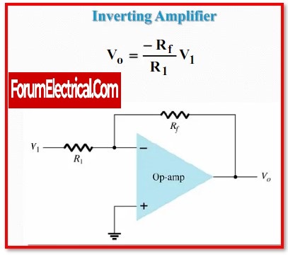
Configuration of Inverting Operational Amplifier
An inverting op-amp circuit schematic is illustrated below.
The negative terminal in this circuit is linked through feedback to provide a closed-loop action.
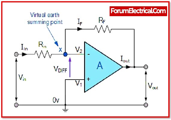
While operating with op-amps, users must remember two important rules: there is no current flow in the input terminal and V1 is always equal to V2.
Since the positive input terminal is grounded, it is at O v. The op-amp in the preceding arrangement is coupled utilising feedback to generate a closed-loop operation.
There are two extremely crucial principles to know regarding inverting amplifiers when working with operational amplifiers: “No current flows into the input terminal” and “V1 always equals V2.”
Apparently, the above-mentioned two principles are violated to some degree in actual op-amp circuits since the input junction & feedback signal ‘X’ are at equal potential.
When the positive (+) input is 0 volts, the junction is referred to as a “Virtual Earth.”
As a condition of this virtual earth, the op amp’s input resistance equals the value of the input resistor (Rin).
The ratio of the two external resistors may be used to control the closed-loop gain of the inverting op amp.
After passing the input signal via the ‘Ri‘ resistor to the op-inverting amp’s terminal, the non-inverting terminal is connected to ground.
In addition, feedback is supplied to help steady the circuit. The output may now be regulated by a feedback resistor ‘Rf‘.
Working & Operations of Inverting Op-Amp
The voltage gain achieved by the above circuit is stated as
Av = Vo/Vi
Where,
Vi-V1 = IiRi
V1-V0 = IfRf
Yet, since there is no current flowing into its input terminals, a perfect operational amplifier has infinite input impedance.
I1 = I2 = 0
As a result, Ii is identical to If.
So,
Vi-V1 = IfRi
V1-V0 = IfRf
As known that the voltage at two op-amp inputs is always equal in a perfect operational amplifier.
Since the non-inverting terminal is grounded, the voltage at the non-inverting terminal is
V1 = V2 = 0
As a result, the equation will be,
Vi-0 = IfRi
0-Vo = IfRf
From the above obtained equations, can get
-Vo/ Vi = IfRf/ IfRi
Vo/ Vi = – (IfRf/ IfRi)
Vo/ Vi = – (Rf/Ri)
This equation may be changed to obtain Vout is
Vout/ Vi = – (Rf/Ri)
Vout = – (Rf/Ri) x Vin
The voltage gain of an inverting op-amp is,
Inverting Op-Amp Gain (Av) = – (Rf/Ri)
This specifies that the voltage gain of an inverting amplifier may be determined by dividing the ‘Rf‘ by the ‘Ri‘, including the negative (-) sign that signals the reverse phase.
Also, the input impedance of the inverting amplifier is ‘Ri‘.
These amplifiers, like DC amplifiers, have excellent linear properties, making them suitable. Moreover, they are usually employed to convert the i/p current to the o/p voltage in transresistance(or)transimpedance Amplifiers form.
The output voltage (Vout) equation demonstrates that the op-amp circuit is linear for an amplifier with a fixed gain, as
Vout = Vin x Gain
As a result, this characteristic is highly useful in converting a little sensor signal to a higher voltage.
Voltage Characteristics of Inverting Op-Amp
The voltage characteristics of an inverting amplifier are seen in the graph below. It should be noted that when the input signal is positive, such as Vin, the output voltage, such as Vout, is negative.
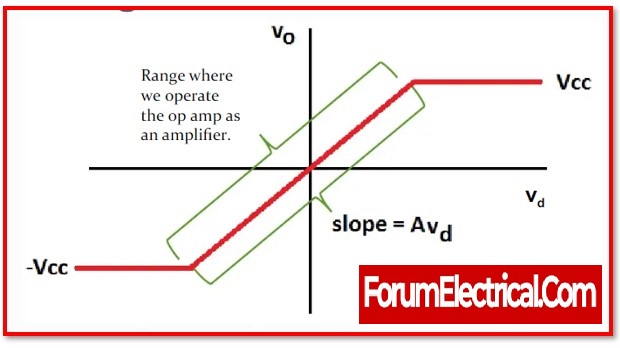
Also, after the input voltage is applied, the output voltage will vary linearly.
After the amplitude of the input signal exceeds both of the supplied power supply to the op-amp, this characteristic will saturate and the output will become constant.
+VCC = + VSAT
&
–VCC = -VSAT
Waveforms of Inverting Op-Amps
The input and output waveforms of an inverting op-amp can be drawn assuming the amplifier’s strength and a sine wave as an input signal.
The following waveforms simply illustrate that the output is twice as large as the input, since
Vout = Avx Vin
and the phase is the reverse of the input.
Why are Inverting Op-Amps preferable than Non-Inverting Op-Amps?
The offset voltage in an inverting op-amp is included in the output, therefore it is less than a few mV, however in a non-inverting op-amp, the offset voltage may be altered by the non-inverting gain, and this value is again included in the output voltage.
Inverting amplifiers provide more system stability than non-inverting amplifiers. Negative feedback is used in inverting amplifiers, which is always necessary for a stable system.
Difference between Inverting & Non-Inverting Op-Amps
| S.NO | Inverting Op-Amp | Non-Inverting Op-Amp |
|---|---|---|
| 1 | Voltage shunt feedback is used. | Voltage series feedback is used. |
| 2 | This amplifier’s input and output voltages are 1800 degrees out of phase with one another. | Voltages at both the input and output are in phase. |
| 3 | Voltage Gain (Av)=(Vout/Vin)=(−R2/R1) | Voltage Gain (Av)=Vout/Vin=1+(R2/R1) |
| 4 | R1 is the input impedance value. | The impedance on input is quite high. |
Advantages of Inverting Op-Amps
- They are not prohibitively expensive.
- It is of a small size.
- Versatility
- Dependability
- Flexibility
- This op-two amp’s input terminals will never read anything other than zero. In addition, the differential mode signal will be present in its simplest form.
- Strong anti-interference capability is included in the gadget that has an inverting amplifier.
- It makes advantage of the negative feedback loop.
- The gain factor is quite large in its magnitude.
- This op-amp will provide an output that is out of phase with the signal that is being input.
Disadvantages of Inverting Op-Amps
- The input impedance is relatively small (equal to R1)
- While it has a high gain, the feedback has to be maintained so that there is minimal distortion.
- It is important to ensure that the signal being input does not include any noise, since this will cause the output value to be magnified and increased.
- The signal has been reversed.
Applications of Inverting Op-Amps
- An inverting amplifier may function as a trans-resistance amplifier, also known as a trans-impedance amplifier. This amplifier functions as a current-to-voltage converter and is utilised in low-power applications.
- When a system is developed with several kinds of sensors, an inverting amplifier is employed at the output terminals.
- Since this op-amp maintains an identical voltage potential at both terminals, it may be employed in a variety of applications.
- These op-amps are employed in the notion of mixers when RF signals are present.
- It may function as a phase shifter.
- These op-amps are employed in situations when signal balance is required.
- It is often used in integration applications.
- Op-amp-based inverting circuits are more stable, have reduced distortion, and give a better transient response.
- Op-amps are employed in any electrical device that has linear integrated circuits.
- They are employed in signal processing and analogue filtering.
- They are utilised in a wide range of applications, including communications, process control, displays, computers, measurement systems, power sources, and signal sources.
- They may be used in linear op-amp applications.
Frequently Asked Questions
1). Why do need an inverting amplifier?
As inverting op-amps have a higher slew rate than non-inverting type configurations, they are mostly employed in high frequency applications where high input/output impedance is not required.
2). What is the purpose of a unity gain amplifier?
A voltage follower may also be referred to as a unity gain amplifier, isolation amplifier, or voltage buffer. Inside a voltage follower circuit, the output voltage (Vo) is equal to the input voltage (Vin). As a result, the gain of this amplifier is one and it has no effect on the incoming signal.
3). How do calculate an inverting amplifier?
The formula of inverting amplifier
Av = – (Rf/Ri)
4). How may an operational amplifier be utilised as a non-inverting amplifier?
An op-amp may be utilised as a non-inverting amplifier by connecting the input of op-amp to the positive terminal & connecting the output voltage signal as feedback to the inverting terminal’s input.
5). What is the theory of an inverting amplifier?
An op-amp inverting amplifier is a kind of op-amp amplifier in which the output waveform is phase opposite to the input waveform. The amplitude of the input waveform will be amplified by the factor Av (the amplifier’s voltage gain), and its phase will be inverted.
")

")


