Table of Contents
Purpose
This procedure is designed to conduct a systematic series of pre-commissioning tests on isolators to make sure the equipment’s functionality and health.
Scope
The pre-commissioning test for isolators is addressed in this procedure, as follows:
- Insulation Resistance Test
- Contact Resistance Test
- Infrared Test of Isolator Motor Winding
Responsibility
Unit Heads/Regional Managers
- Planning and scheduling of activities to ensure the successful execution of the project
- Identifying and addressing significant health and safety hazards
- Meeting all legal & statutory requirements
- Assist the safety team in conducting the safety training and audit at the sites.
- Ensure that all safety rules & regulations are adhered to at the work sites.
Site Engineers
- Site engineers responsibilities include reporting any health and safety concerns at work sites to the regional manager, unit head, or safety team.
- Coordinate with customers to obtain and return work permits.
- Communicate work content and hazards to working groups through toolbox meetings before each day’s start.
- Implement proactive measures to reduce accidents.
- Report incidents in detail.
- Use proper PPE.
- Maintain job quality without compromising safety.
- “Stop Work” for significant safety violations.
Safety Engineers
- Safety engineers responsibilities include ensuring the application of occupational health and safety instructions and procedures.
- Communicate safety rules, regulations, and practices to site engineers, regional managers, and unit heads. – Follow up on audit non-conformances and assist regional managers/unit heads in taking corrective and preventive action.
- Report and investigate incidents and near misses to top management.
- Organize frequent training programs and raise awareness among site engineers and regional managers.
- Conduct daily toolbox discussion sessions to ensure workers are aware of workplace hazards.
- Ensure the use of PPE and safety equipment at work sites.
- Report any health and safety issues to the unit head or regional managers. – Provide basic first aid facilities on-site.
- Ensure no harmful acts are undertaken on any site.
- Eliminating harmful conditions on-site promptly.
- Issuing safety challans for violations.
Work Activity
Pre-Testing Checks
- Examine the operating status of the ELCB (30 mA).
- Inspect power cable insulation for equipment.
- Ensure that adequate earthing & rubber matting are available on the jobsite.
- Utilize calibrated testing equipment & report calibration results to engineers.
- Check the technician’s insulation hand tools.
- Check test leads for insulation damage.
- Make sure suitable PPE is accessible at the site.
Equipment Required
For IR Test
- Insulation Tester (500 and 5000 V)
- Test Leads.
- Insulated Hand Tools
For Contact Resistance Measurement Test
- This package includes a contact resistance meter with test leads ranging from 200µΩ to 2000µΩ for measuring motor winding resistance.
- A multimeter with test leads.
For Motor Insulation Resistance Test
- Insulation resistance tester (500/5000V)/megger
- Test leads.
Test Procedure
Insulation Resistance (IR) Test for Isolators
- Obtain the work permit from the customer.
- Test equipment for zero energy before starting work.
- Place isolators in close positions.
- Connect the megger’s positive lead to the isolator pole.
- Connect the earth lead to the ground.
- Turn on the megger & press the test button to record the data.
- Connect positive lead to one pole & negative lead to another while isolator is open.
- Turn ON the megger.
- Inject the voltage & record the readings.
Motor Winding IR Test (with 500V Megger)
IR Test from Phase to Phase
- Connect the megger to the motor terminals “U1 & V1”.
- Turn on the megger and click the test button to record the data.
- Discharge potential from “U1 & V1” terminal to earth.
- Turn off the megger.
- Repeat for remaining terminals (V1 & W1 and W1 & U1).
IR Test between Phases and Earth
- Shorten the motor terminals (U2, V2, and W2).
- Connect the megger to the motor terminal “U1” and Earth.
- Turn on the megger and click the test button to record the data.
- Discharge potential from “U1” terminal to earth.
- Turn off the megger.
- Repeat for other terminals (V1 and W1).
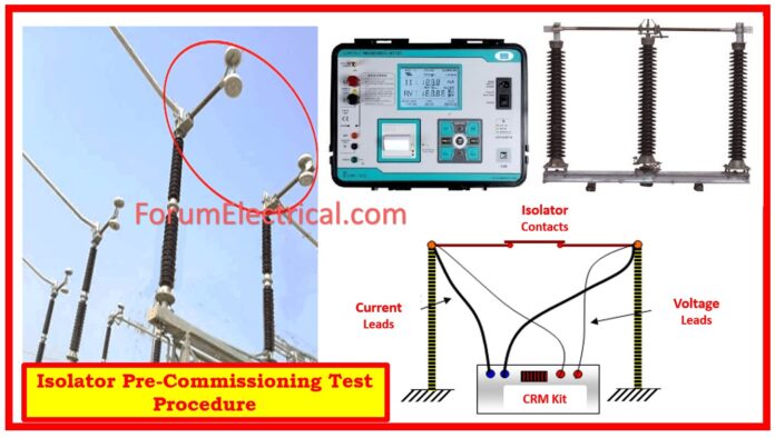
Contact Resistance Measurement Test
- Obtain work permit from customer.
- Test equipment for zero energy before starting work.
- Connect CRM kit to Isolators’ moving and fixed contacts when they are closed.
- To test the CRM kit, turn it on and click the test button.
- Record the readings.
- Connect the CRM kit to the connectors of the isolators when they are open.
- Turn on the CRM kit, test the press button, and record the readings.
Control Measures
- Testing engineers provide OCP (Over Current Protection) for IR & CRM for Isolators.
- Make sure PTW system in place for the specific bay.
- Make sure all equipment is turned off.
- No unauthorized individuals should be allowed to enter the testing area.
- Use warning tape to barricade the area.
- Use a normal insulated ladder for heights less than 2 meters.
- Inspect ladders before work.
- Keep both feet below the third rung from the top.
- Use one hand on the ladder at all times.
- Proper supervision, including job-specific toolbox meetings and barricades.
- To ensure safety, utilize calibrated equipment, insulated hand tools, avoid power cable joints, and supply via ELCB.
- Avoid working alone and wear proper insulated gloves.
Final Check & Restoration of Work
- Disconnect the temporary supply & remove barricades.
- Remove any unsecured tools from the area.
- Maintain a tidy and clean environment after leaving.
You can also follow us on AutomationForum.co, Facebook and Linkedin to receive daily Instrumentation updates.
You can also follow us on ForumElectrical.com, Facebook and Linkedin to receive daily Electrical updates.


