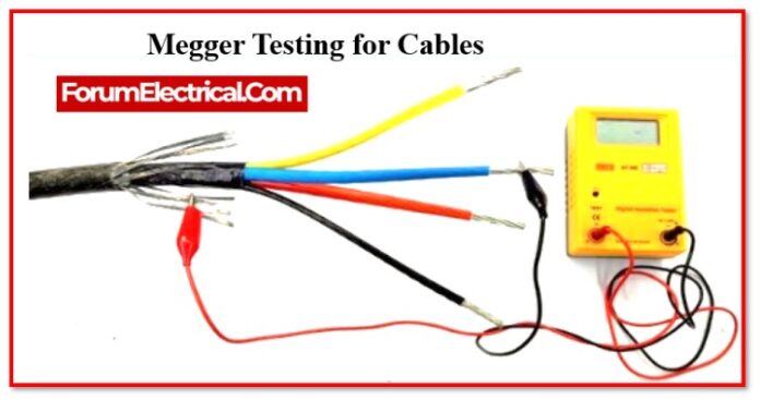
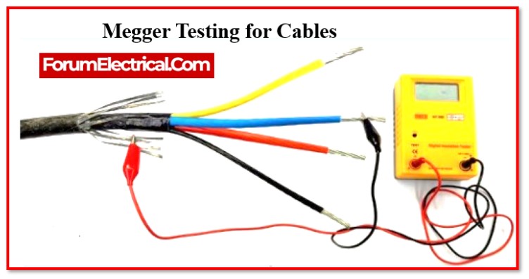
What is meant by Megger testing?
Megger testing is a type of electrical test that evaluates how well insulation performs in a part of electrical equipment. A voltage is provided, and then a mega-ohm meter is used to measure the resistance of each phase connection between the motor leads and the ground.
General Procedure for the Megger Test
Check the level of electrical insulation in any device, such a motor, cable, or transformer, to determine how much electrical leakage there is in the wire.
This can be done by passing the current through the devices initially. The magnitude of the effect of this can be expressed in terms of (MΩ)mega ohms.
Mechanism of Megger
- It is necessary to have 1000V to 5000V for the testing purposes when working with electrical systems that have a high voltage.
- The connection of the deflecting coil needs to be in series in order for the current to flow and function properly throughout the circuit.
- A power supply coil is placed in the middle of this connection to complete the circuit.
- Both the Current Coil Resistor and the Pressure Coil Resistor are linked in series with each other so that the circuit can be shielded from any potential damage.
- Using the use of two coils, such as a control coil and a deflecting coil.
- An EMI effect will produce a test voltage when it is applied to a megger that is operated by hand.
- When the voltage gets increases, the deflection pointer will show that it has increased all across to infinity. In the same way, if the current makes the deflection greater, the pointer remains at zero.
Instruments & Equipment
1). The Megger Instrument must be calibrated.
2). A megger with a range of 500V/1000V must be used to conduct the test.
- Wire testing shall be performed using a 500 V megger.
- For cable testing, a megger with a range of 1000 V needs to be utilised.
Pre-Analysis Study & Preparation
- The leads that are used to connect the megger to the circuit need to be free of any faults, and the two leads that are used to connect the megger need to have electrical continuity.
- It is checked by connecting the free ends of leads together and contacting them while simultaneously pressing the ON button on the megger in order to check for a resistance of zero.
- PVC adopters are included for cables, along with male adaptors for any and all PVC conduits that terminate in panel board.
- Make sure that the insulation has been applied to each and every wire in the panel boards.
- Before starting the testing, make sure that all of the connections have been completed.
Electrical Continuity Test
Connect the free test probes to the any two wires that need to be checked with the megger.
For Wires: When all of the devices are connected, both ends of the conductors are shorted, and all of the switches are turned on, the reading that is displayed on the megger must be zero. If the reading indicates that there is no limit, then the circuit is open. It is necessary to identify the source of the problem and correct it.
For Cables: In the case of cables, the outermost ends of any two phases should be shorted, and the reading should be zero when the test is carried out; if the meter reads infinity or some number of mega ohms, this indicates that there is a fault in cable, and it ought to be fixed as soon as possible. The exact same process needs to be repeated for the cable’s other three conductors.
Insulation Resistance Test
For Wires: The voltage range on the Megger should be set to 500V when testing the circuit’s wires
- Between neutral and phase
- From the phase to the earth
- From neutral to earth
The value should be infinity during the entire test with each of the other ends of circuit conductor open. If the result is 0, there has been a short circuit (or) the wire’s insulation has been damaged, in which case the wire should be replaced.
For Cables: The Megger range for cables needs to be 1000V, & both ends of the cable must be left open during testing between the phases and neutrals.
Between Phase-to-Phase
- R-to-Y
- R-to-B
- Y-to-B
Between Phase-to-Neutral
- R-to-N
- Y-to-N
- B-to-N
All of these readings supposed to be infinity; if they are not, the cable’s conductors and phases are defective and need to be fixed.
In order to properly test the insulation, detach from the panel (or) equipment and then ensure that they remain isolated from the electrical supply.
With the use of a ground (E) cable, the cables need to be checked against one another (phase to phase). Formula for determining minimum insulation resistance values is provided by the Insulated Power Cable Engineers Association (UPCEA).
R=K X Log10(D/d)
Where,
R=IR Value expressed in MΩ for every 305 metres (1000 feet) of cable.
K = Constant for the insulation material (Varnished Cambric = 2460, Thermoplastic Polyethylene = 50000 Composite polythene 30000)
K = Constant for the insulation material (Varnished Cambric = 2460, Thermoplastic Polyethylene = 50000 Composite polythene 30000)
D – Outside diameter of the conductor insulation for single-conductor wire and cable (D=d+2c+2b = diameter of a single-conductor cable).
d -size of the conductor’s diameter
c – thickness of the insulation surrounding the conductors
b – thickness of the insulation surrounding the outer-sheath


