
In the past, the power system was only limited to planning and design; today, the transient stability studies are essential both in operational planning and also in real-time operation since power systems are a nonlinear problem.
- What is Transient Stability?
- Factors Affecting Transient Stability
- Methods of Improving Transient Stability
- Joint Use of DC System
- Using UPFC
- Using Multiple Models & Switching
- Waveform Relaxation Method Transient Stability Simulation
- Phase-Shift Insertion
- By Turbine Fast Valving
- Use of Automatic Re-Closing
- Other Methods
- What is Transient Stability Limit?
Power-state stability refers to the system’s ability to return to its steady state condition after being subjected to specific disturbances.
To further understand power system stability, we may now look at synchronous generators.
The generator is synchronized with the other systems that are connected to it.
So, we may say that power system stability refers to the power system’s ability to return to a steady state without compromising synchronism if subjected to disruptions.
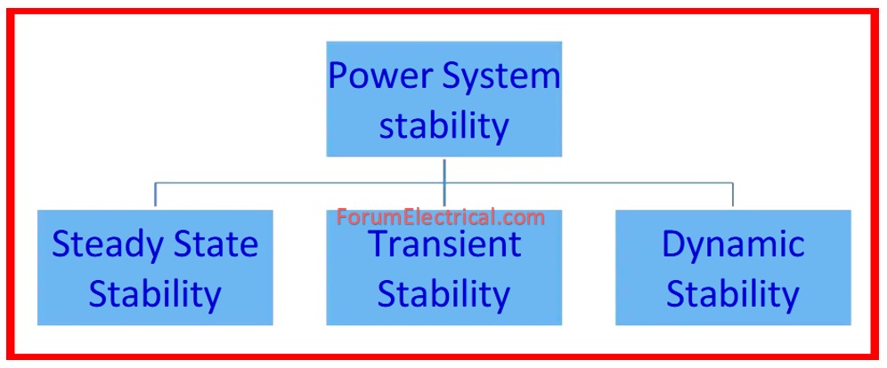
This system stability is classed into three types:
- Transient Stability,
- Dynamic Stability, and
- Steady-State Stability.
Steady State Stability: Steady state stability refers to a power system’s capacity to maintain synchronism irrespective of small, gradual changes in the operating conditions.
Dynamic Stability: The study of power systems that experience tiny continuous disturbances.
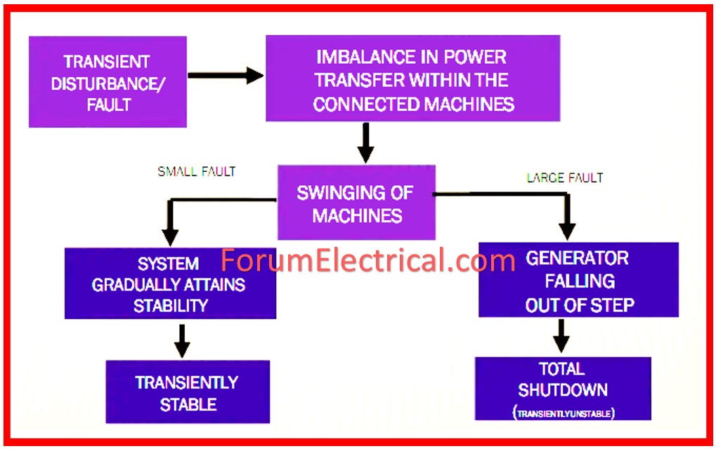
What is Transient Stability?
Transient stability is the capacity of the power system to sustain synchronism following an unexpected major disturbance.
These disturbances could result from faults being applied, faults being cleared, EHV system switching ON & OFF surges.
“Transient” refers to Change
Therefore, for transient stability the system stage is changing where, if the transition is regarded from one equilibrium to the other, significant disturbances result.
Thus, the most important requirement is to enhance the transient stability.
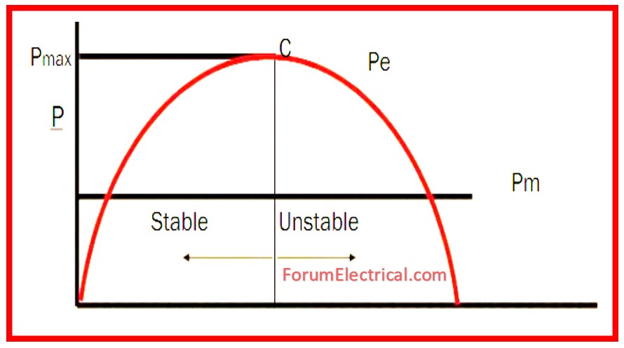
In general, the steady state stability limit is defined as
Pmax = VE/X
Pmax can be enhanced by increasing either (or) both V & E while decreasing X.
Factors Affecting Transient Stability
The post-disturbance system reactance as observed from the generator: Pmax will be smaller the weaker the system reactance turns out.
The longer the fault is in effect, the longer the rotor is going to remain accelerated along with the greater amount of kinetic energy will be obtained. It becomes more difficult to discharge accumulated energy during deceleration the more energy is obtained during acceleration.
Higher the generator’s inertia, smaller the rate of change of angle & the less kinetic energy obtained during the fault.
The Pmax will be lower the voltages, hence the generator internal voltage will be also.
The generator loading prior to the disturbance: The unit will be closer to Pmax the higher the loading, so during acceleration it is more prone to become unstable.
The generator internal reactance: The peak power increases as the reactance decreases; the initial rotor angle lowers.
The type and location of the fault determines the generator output during it.
Methods of Improving Transient Stability
Joint Use of DC System
With improved transient stability, the DC power of the steady state is greater as compared with the ac power in parallel ac-dc systems; hence, the stability problem usually occurs and the researches have been conducted with corresponding results.
In case of an AC system’s defects, the transient stability is enhanced if the dc power is fast rising.
The generator accelerates at the sending end in 3-phase short circuit when the sending ac system produces a significant reduction of the dc power.
For the countermeasure, two control methods exist.
Using UPFC
This work mostly addresses the following question: How to Unified Power Flow Controller (UPFC) parameters & how it must be managed to get the maximal intended effect for fixing initial swing stability problem.
Mostly for large power systems with extensive transmission lines, these types of problems exhibit out.
Various methods of reference identification of the series component are being studied in order to enhance the transient stability of the system depending on ideal parameters, state variables & also injection models.
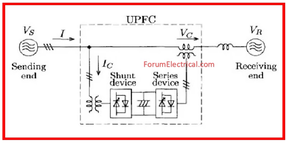
At last, a technique based on state variables employing the local measuring was suggested.
Using Multiple Models & Switching
The inadequate transient response seen when adaptation is started is the most typical problem with adaptive control.
Here an efficient method is established for enhancing the transient responsiveness by means of multiple models of the plant for control and switching between them.
These models are similar save for first approximations of the unknown plant parameters & control is applied to ascertain at every instant by the model that best approximates the plant.
The outcome of our simulation shows the attainability of performance improvement.
Waveform Relaxation Method Transient Stability Simulation
This is an innovative method for power system dynamic response computation is suggested.
Extensively applied in transient analysis of VLSI circuits, this method is known as the waveform relaxation and may gain advantage from new designs in computer systems including parallel processors and provides computational results.
Phase-Shift Insertion
Using a double-circuit transmission line and an infinite bus bar, the computational research of transient stability of synchronous machines are coupled to show the influence of relative phase-shift in which the insertion across the machine & its corresponding power system occurs.
Together with an explanation of possible implementation by a phase-shifting transformer in a power system, this approach of obtaining an alteration in the effective rotor-excitation angle and therefore the power transfer is presented.
By Turbine Fast Valving
One of the main causes of power system instability is excess energy generated by turbine over the fault time.
Fast Valving reduces the mechanical input power whenever the generator is under-acceleration during failure, which increases the system’s stability.
Use of Automatic Re-Closing
The majority of power system failures will be transient and self-resolving.
As a result, circuit breakers used for the fault clearance open after sensing the fault with a time delay of two cycles and close after a specific amount of time to assess whether the problem has been cleared.
Other Methods
- Improved steady-state stability.
- Higher system voltage levels.
- Additional transmission lines.
- Reduced transmission line series reactance
- Smaller transformer leakage reactance.
- Series compensation for transmission lines.
- Static voltage compensators (SVC) & other flexible alternating current transmission systems (FACTS) devices
- High-speed fault-clearing – within three cycles
- Fast re-closure of circuit breakers
- Single-pole switching.
- Larger machine inertia reduces angular acceleration and increases CCT (Critical Clearing Time).
- Braking resistors
- Increase the system voltage to improve its transient stability. Increased voltage characteristics of system suggests increased power transfer capabilities. This helps in improving the difference between the initial load angle & the critical clearance angle. As a result, increased power allows machine to spin across a wider range of angles before reaching the essential clearance angle.
- An increase in the power system’s X/R ratio raises the line’s power limit. This helps to increase stability.
What is Transient Stability Limit?
The transient stability limit is the highest amount of power which a power system can handle before becoming unstable due to a rapid disturbances. It’s less than the steady-state stability limit.


