
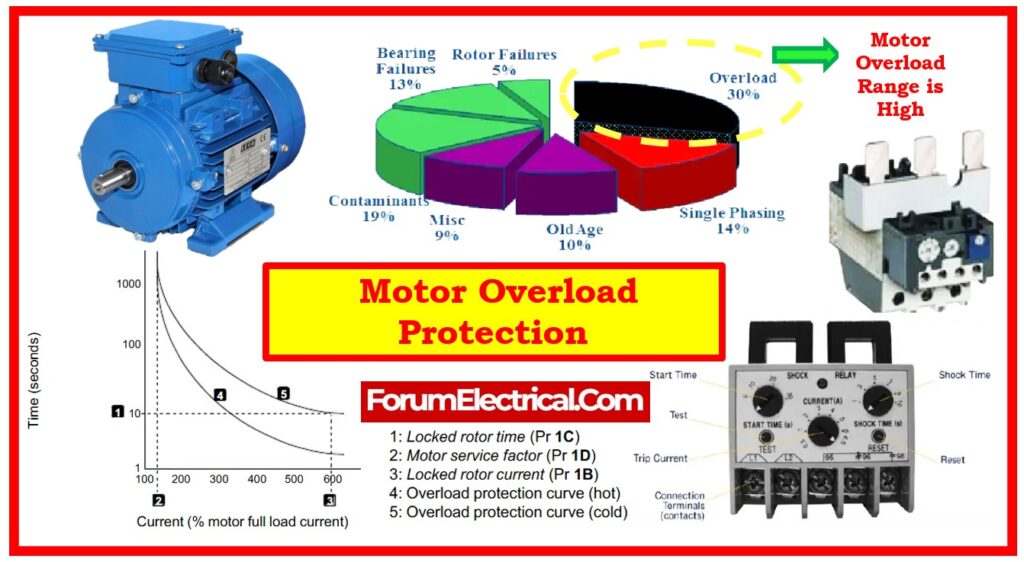
What is Overload Protection?
An overload is the condition that the motor experiences when it pulls surplus current.
This can damage the motor’s windings and lead to overheating of the motor.
This makes it essential to protect from overload conditions the
- Motor,
- Motor branch circuit, and
- Motor branch circuit components.
From the overload state, overload relays protects motor, motor branch circuit, and motor branch circuit components from too high heat.
One of the part of motor starter (assemble of contactor plus overload relay) are overload relays.
By tracking the current across the circuit, they protects the motor.
The overload relay will trip, running an auxiliary contact that de-energizes the contactor, if the current increases over a designated limit during a given length of time.
This causes the motor to lose its ability to run.
The components of the motor & motor circuit do not overheat and damage without power.
While some overload relays get reset automatically after a specified amount of time, others can be reset personally. The motor can thus be turned on again.
NEC 430/32 Overload Protection for Motors
Overload protection (Heater or Thermal cut out protection) is a device that protects a motor from thermal damage caused by being overloaded with work.
All continuous duty motors rated at higher than one horsepower must have an approved overload device.
An overload must be provided on every conductor that controls the operation of a motor with more than one horsepower.
NEC 430/37 requires that the grounded leg of a three-phase grounded system have an overload additionally.
This grounded leg of a three-phase system is the sole place where you can install an overload or overcurrent device on the grounded conductor that supplies a motor.
How do you calculate Overload Protection for a Motor?
Motor Overload Protection Calculation
To determine the motor operating overload protection size necessary, multiply the F.L.C. (Full Load Current) by the minimum or maximum percentage ratings as follows:
Maximum Overload
Maximum overload = F.L.C. (full load current of a motor) X allowed percentage of an overload’s maximum setting
- 130% for motors, as stated in NEC Article 430/34.
- A 5% increase is permitted if the marked temperature rise does not exceed 40 degrees (or) the marked service factor does not fall below 1.15.
Minimum Overload
Minimum Overload = F.L.C. (motor’s full load current) X allowed percentage of the minimum overload setting
- 115% for motors specified in NEC Article 430/32/B/1.
- Increase from 10% to 125% if the marked temperature rise is not more than 40 degrees (or) the marked service factor is not less than 1.15.
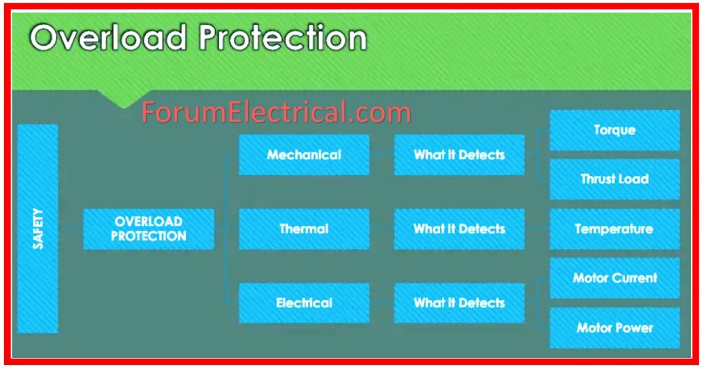
Types of Motor Overload Protection
Since it protects the motor from harm resulting from too high current draw, overload protection is required function of motor.
A motor running more current than its rated capability may overheat and destroy the motor windings. By minimizing the power supply to motor, overload protection finds and responds to this condition.
In motor, the two fundamental types of overload protection are
- Thermal Overload Protection
- Electronic Overload Protection
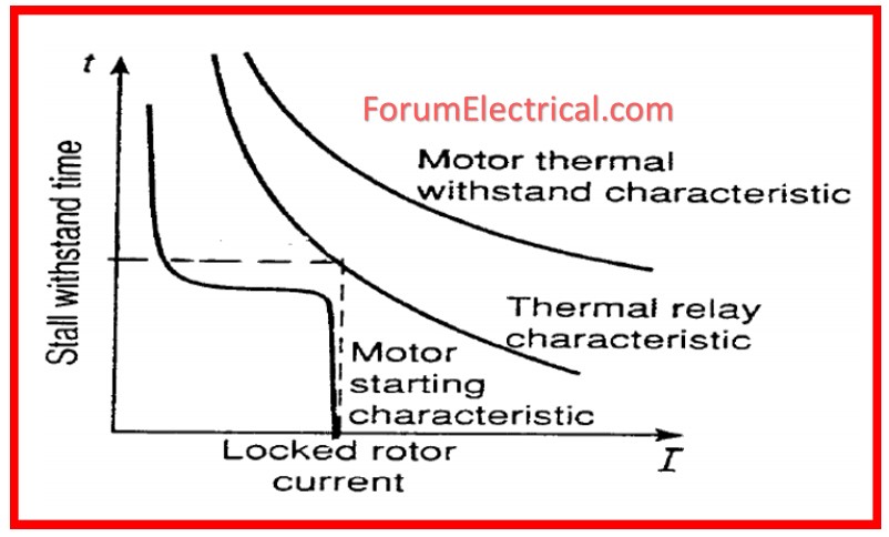
1). Thermal Overload Protection
This type of protection depends on a bimetallic strip (or) thermal element in contact with motor windings.
The thermal element’s temperature rises as the current passes through the windings.
The bimetallic strip or element will bend or shift whenever the temperature approaches a specified point, activating a switch to open the circuit & cut off the motor power supply.
Though less exact than electrical overload prevention, the thermal overload protection (thermal overload relay) is simple & reasonably affordable.
2). Electronic Overload Protection
This type of protection measures the current consumed by the motor by means of an electrical device such a current sensor (or) current transformer.
When the current surpass the specified limit, this device will notify a control module, therefore cutting off the motor’s power supply.
Though it can be more expensive, electronic overload protection is more exact and dependable than thermal overload protection.
If the motor take too much current, an overload device will cut off the circuit.
6 Motor Overload Protection Devices
External Overload Devices
1). Starters: Most electric motor starters feature overload protection integrated as an overload relay. The starter trips and power is taken off the circuit in an overload condition. For motors requiring just start & stop control, starters are superior; but not for speed control.
2). Overload Relays: These relays trip and remove power from the circuit if the overload continues even if they enable the overload required at start-up. Though they can be independent as well, overload relays are usually found in the motor starter.
3). Variable Frequency Drives: Every VFD also features overload protection built in. And the VFD reduces power from system in an overload condition. VFDs are perfect if your motor additionally calls for speed control.
Internal Load Devices
4). Thermistors: Built into the windings of the motor, thermistors protect against both high ambient and internal temperatures. The thermistors will increase the resistance till the motor cools down when a high temperature is found.
5). Resistance Temperature Detectors (or) RTDs: Designed to be wired between the windings, Resistance Temperature Detectors (or) RTDs are the sensors will adjust resistance to protect each windings when the temperature changes.
6). Thermostats: On terminal board of the motor’s circuit box are located these switches. The temperature of circuit determines whether they open or close. An alert circuit or disconnect power from circuit can be controlled using thermostats, therefore allowing time for cooling off.
What is the Overload Protection for a 3 Phase Motor?
The setting up of a thermal relay that is made up of bimetallic sheets is frequently carried out in control circuit of the 3 phase motor.
For the purpose of bending due to thermal expansion throughout overload operation, it makes use of two pieces of metal that have different expansion coefficients. This allows it to promote a set of operations.


