Transformers use mutual induction to transfer electrical energy between circuits without connection.
It uses electromagnetic induction. Transformers have primary and secondary windings. Used to enhance or decrease circuit voltage.
Transformers are the heart of electrical distribution systems. If the transformer fails, the distribution system may be destroyed and electrical energy cannot be transferred.
- Mechanical failures,
- Electrical damage,
- Thermal damage, &
- Winding deformities
can harm the electrical circuit.
Thus, transformer testing should be done to prevent breakdowns.
To determine an electrical transformer’s characteristics and performance, test it. Transformer testing should occur throughout manufacture to meet design and specification requirements.
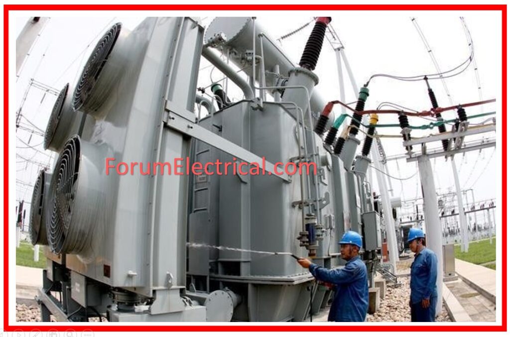
Transformer Testing performed at the Site
Pre-Commissioning Tests
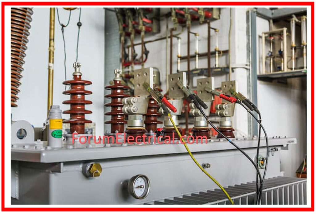
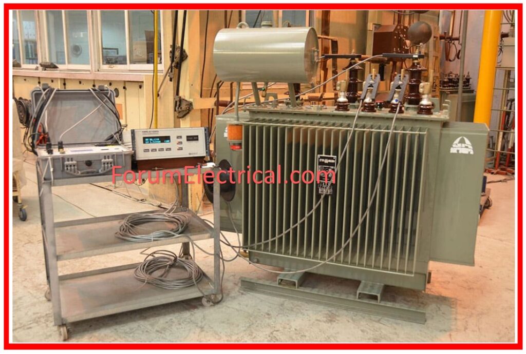
Pre-commissioning testing for transformers include:
- Operational inspection of the protection system
- Insulation resistance (IR) measurements
- Measurement of capacitor bushings
- Measurement of voltage ratio (turns ratio)
- Measurement of the transformer’s vector group (or) polarity
- Measurement of winding resistance
- Measurement of vibration in the transformer
- Testing the magnetic balance of the transformer
- A measurement of the transformer’s frequency balance response (FRA).
- Measurement of the floating neutral point.
- Measure the transformer’s short-circuit impedance & magnetizing current.
- Measurement of stability of differential, REF of transformer.
- Measurement of bushing current transformers (BCT).
Visual Inspection
Implement the G.A. (General Arrangement) Drawings & customer specifications to check name plate details, ratings, color markings, internally mounted components, neutral connection, bushing seals, bucholz relays, cable glands, gland plate, and other relevant information.
Transformer Oil Breakdown Voltage Test
Transformer oil breakdown voltage is tested using a BDV test kit with a 2.5mm sphere gap, following BS148 standards.
A sample will be obtained from the bottom side of the transformer’s main tank. If the average of six tests performed on a single sample exceeds 30kV, the oil is deemed in good condition.
Voltage Ratio, Polarity, & Vector Group – Measurement
The transformer ratio, polarity, and vector group must be checked to verify the correct voltage ratio (HV/LV) between various windings on each tapping with an acceptability tolerance of 0.5%.
Winding Resistance Test
Winding resistance of HV and LV is measured with a winding resistance meter. The resistance value can be modified in response to atmospheric temperature. This test can verify the equality of resistance.
Insulation resistance testing for HV and LV windings involves applying a test voltage.
a). 5000 V between HV/E and HV/LV.
b). 1000V for LV/E if the transformer’s LV side voltage is rated at 440V.
c). 5000V for LV/E if the transformer’s LV side voltage is rated at 3.3kV or above.
Temperature switches & Buchholz Relays Functional Check
Check temperature switches and Buchholz relays for proper functionality. All protection switches should be tested for their intended functionality. To test temperature switches, normalize the DC power at the annunciation panel, HT side SWGR, and LT side switchgear. Place both end CBs in the test position, closed. Reset all auxiliary relays.
a). To test the temperature switch, use the knob to trigger an alarm on the Annunciation panel. Turn the knob further to achieve a trip at both end CBs. Check the corresponding Aux relays at the switchgear.
b). Slowly press the Buchholz Relay knob to trigger an alarm on the annunciation panel. Turn the knob further to achieve a trip at both end CBs. Check the corresponding Aux relays at the switchgear.
Condition Monitoring Test
These tests are employed to improve the transformer’s performance and evaluate its condition on a regular basis.
The transformer’s condition is periodically tested to ensure that it satisfies the customer’s needs.
These tests are performed on-site following transformer operation on a regular basis, such as weekly, monthly, and annually.
The transformers’ periodic maintenance schedules vary depending on the type of transformer utilized.
These procedures help to detect defects in the early stages by frequently evaluating the transformer’s performance.
Ex: If the insulating resistance of the transformer is measured below the normal value, it indicates that the fault is in its early stages.
Emergency Test
These tests are performed on-site to identify any faults or damage to the transformer that occurred during operation.
Ex: Even though the ventilators function efficiently, high-temperature evaluation involves resistance in windings and oil analysis for transformer cooling.


