What is a PLC Counter?
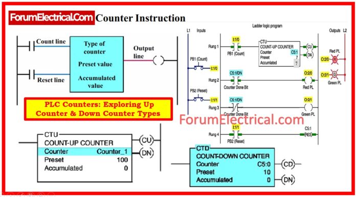
A counter is a PLC instruction that increments (counts up) (or) decrements (counts down) an integer number value in response to the transition of a bit from 0 to 1 (“false” to “true”).
How does the PLC Counter Work?
PLC counter instructions include:
- Counter Type
- Counter Address
- Counter PRESET Value
- Accumulated Count
Each PLC contains counter instructions.
Even though many PLC counters work in a similar way, the command symbols and programming methods vary between manufacturers.
The typical counter counts from 0 Up to the desired value, called the PRESET value.

The current (or) total count is equivalent to the cumulative value.
PLC counters rely on the leading edge of the input signal to count.
When the count input changes from “off” to “on”, the counter will either increment (or) decrement.
The counter will not run during the input condition’s trailing edge or on-to-off transition.
Counter Counting Sequence
Usually, PLC counters are retentive. When the CPU is powered back up, the count that was on the counter when it shut down will be restored.
The counter can be reset, yet, if the reset condition is invoked after power restoration.
It is possible to configure PLC counters to count up (or) down to a predetermined value.
Every counter is coded in the same manner. To program the counter, users must first specify its location and setting.
A counter reset (up or down) is constantly available to reset the counter’s accumulated value to a predefined value.
Counter Limits
Counters use variables of specific data kinds to store numbers in the PLC. Every counter needs to hold a minimum of two numbers:
- Counter Limit
- Current Counter Value
Current Counter Value
Because these two numbers are maintained in a specific data format, they also have limitations.
Many PLCs preserve these 2 numbers as WORD (or) Integer data types, and if you understand the fundamentals of PLC data types, you will recall that a WORD occupies 16 bits.
A signed integer takes up 16 bits, however the initial one is utilized for signing, leaving only 15 bits for the actual number.
By performing an easy calculation, we are able to easily ascertain that the highest possible value of WORD is 16.535.
The maximum value for a signed integer is 32.767.
Although it is uncommon to have to count to such large numbers, it is essential to understand how to avoid overflow issues.
IEC 61131-3, which describes programming languages & counter function blocks, is one of the important standards pertaining to PLC counters.
High-Speed Counters (HSC)
Standard counters may not be able to keep up with exceedingly quick pulses, such as those generated by encoders.
You’ll require a high-speed counter module that can handle these fast signals.
Often referred to as high-speed counters, these input modules are made to accept inputs at different high frequencies.
Counter Function Blocks
Often referred to as high-speed counters, these input modules are made to accept inputs at different high frequencies.
In fact, we discussed two of these previously (counter limit & current counter value).
It is essential to understand here is what data type the inputs & outputs use.
Normally, counters use boolean & WORD data types, but this might vary depending on the PLC platform being used.
So, make sure to verify the instruction manual for the counter on the PLC platform you’re using.
Difference Between Timer and Counter in PLC
Both timers & counters provide the same function: programming instructions to control and run the device.
The major difference is that counters count consecutive digital pulses in binary form, whereas timers count and control operations based on time intervals.
In addition, timers use an internal clock, whereas counters depend on external program sources for counting.
PLC Counter Types
Counter instructions are divided into three fundamental types:
• Up Counters,
• Down Counters,
• Up/down Counters.
Both “up” & “down” counter instructions have one trigger input for counting, while “up/down” counters have two: one to increase and one to decrease.
Up Counters
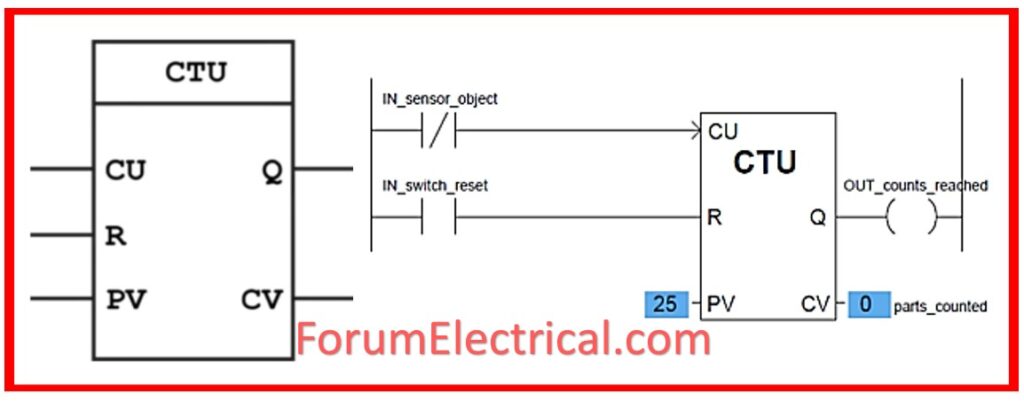
The up counter is an increment (progress) counter that counts “up” for each transition input that goes from FALSE to TRUE (OFF to ON) to its “CU” input.
How Up Counter Works?
Each pulse on count input (CU) increases the current counter value (CV) by one.

When CV exceeds or equals the counter limit (PV), the output (Q) is set. A pulse on reset input (R) will reset CV to zero.
When a TRUE value is entered in the CU input, the counter will switch on, and CV will display the count.
The output of this counter must be activated when the current value is equal to or greater than the value that was previously set (Q is active when CV is greater than PV).
The counter’s output instruction will Increase by one each time the counted event occurs.
The coil format is another way of representing a counter in a PLC ladder logic program.
Up counters are frequently employed to monitor the frequency of an occurrence.
Assume a procedure should be completed 10 times before cleaning is necessary.

For this, set the counter limit (PV) to 10. For the purpose of indicating that the process has been finished, pulse the (CU) count input. Once the process has completed 10 times, the output (Q) will be set. You can utilize the output to set an alarm indicating the system needs cleaning.
After cleaning, pulse the reset input (R) to restart the process.
DOWN Counters
In certain conditions, it’s important to understand how many counts remain until the limit is achieved.
The UP counter requires significant computation, but the DOWN counter is easier because it counts down from a given amount until it hits 0.
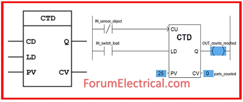
The DOWN counter instruction shall count down (or) decrement by one each time the counted event happens.
Each down-count event reduces the accumulated value.
As you can see, the down counter uses a pin named LD instead of the reset.
It is called load and is used to enter a value into the current counter value. Since when the count down to 0, you’ll need an initial value for the counter.

How DOWN Counter Works?
If CV is = (or) < 0, the output (Q) is set as appropriate value.
Consider a semi-automatic process in which the operator must do a manual task to initiate a process.
The operation must be repeated ten times, but when there are just 2 remaining, the operator must inspect.
It is essential that the operator be aware of how many processes persist, as the total number of processes may differ.
The sum must now be added up as the (CV) current counter value.
The (CD) count input is pulsed once the procedure is completed.
You may now utilize CV to indicate to the operator how many processes remain.
When he sees that there are only two left, he should inspect.
By employing an equality operator to compare the CV to 2, we can also add an alarm.
UP/DOWN Counters
UP/DOWN counters combine UP/DOWN functions.
It is possible for this counter to count both up & down the same counter value (CV).
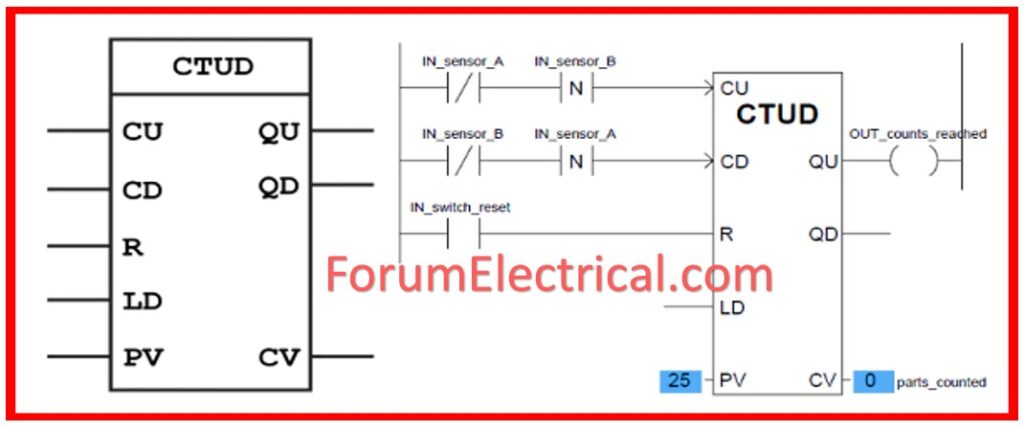
Two count inputs are shown at the topmost point of the function block.
One for numbering upwards, one for counting downwards.
How Does the UP/DOWN Counter Works?
Each pulse on count input (CU) increases the current counter value (CV) by one.

(CV) greater than (PV) counter limit is what determines the size of the (QU) output. (QU) output is determined by CV > PV counter limit.
When CV is lower than zero, QD is set.
(R) – Pulses on reset input reset as CV=0. If sensor A is inactive, the counter only will increase when sensor B deactivates.
When sensor A is de-energized, the counter (countdown) will drop only if sensor B is already de-energized (beam B breaks before A).
The UP / DOWN counter has (R) “reset” & (“LD”) “load” inputs to force current value.
The reset pin “0”is the counter, whereas the load input is set as PRESET.
Use the UP/DOWN counter to count finished goods.
Imagine creating a set amount of objects in the batch control system.
Each product must be manually checked after completion. Remove waste products from the total quantity of finished goods.
We can use the up/down counter.
The count up input can attain a pulse when a goods or product is done.
If the product fails quality testing during inspection, pulse the count-down input to decrease production.
Cascading Counter Instructions in PLC
Depending on application, it may be essential to count events that exceed the maximum number permitted by each counter command. One method for achieving this count is to interconnect, or cascade, two counters.
The PLC program below demonstrates this method.

The program’s operations can be described as follows:
- The second counter’s input is programmed with the output of the first.
- Both counters’ status bits are programmed in series for output.
- These 2 counters measure twice as many counts.
Industrial control systems must meet NEMA ICS 3 standards for programmable logic controllers (PLCs) and counting functions to ensure reliable operation and integration.
Allowed CTU Data Types
Most PLC systems employ the Counter data structure, which the CTU uses.
- Counter – The highest-level instruction specification for all inner structures.
- .PRE – An integer that specifies the maximum value for which the timer will count.
- .ACC – An integer indicating the current time value of timer.
- .CU – A Boolean value set to HIGH when counter is activated to count up.
- .CD – A Boolean value set to HIGH when counter is activated to count down.
- .DN – A Boolean value that is set to HIGH once the timer is finished counting.
- .OV – A Boolean value that is set to HIGH when counter overflows.
NOTE: The overflow condition indicates that the counter has attained the logical limit of 32767 & must wrap back to the value of -32768.
- .UN – A Boolean value set to HIGH when counter is underflow.
NOTE:
The underflow condition indicates that the counter has surpassed the logical limit of -32768 & must wrap back to the value of 32767.
To avoid overloading the counter, ensure the software includes suitable protections.
What is Reset Counter Function?
Resetting a counter in PLC is a vital process for ensuring the system’s proper operation.
The initial step is to clearly identify specific counter that needs to be reset, as well as the specific requirements that trigger the reset operation.
This involves understanding the counter’s operational requirements & objectives within the overall PLC program.
After establishing the counter & reset conditions, the next step is to build the logic that will effectively conduct the reset operation.
This includes creating the necessary instructions (or) code to monitor the relevant inputs & trigger the reset process when the predefined criteria are met.
During the programming phase, it is essential to consider variables such as safety measures, system integrity, & any potential influence on existing processes.
Furthermore, installing robust reset logic necessitates extensive testing & validation to assure correctness and reliability under a variety of operating conditions.
Engineers should run extensive simulations & real-world tests to ensure that the reset mechanism works as expected and does not cause any system disturbances or failures.
By following these systematic steps and being careful in the programming process, PLC specialists can create an accurate counter reset mechanism that improves the overall efficiency & performance of industrial automation system.


