
What is Polarity Test?
Polarity can be described as the induced voltage direction in the transformer’s two windings, main and secondary.
If two transformers can be connected in parallel, the polarity should be established to ensure a suitable transformer connection.
Polarity Test in Circuit
A test that forms a circuit between the phase conductor & the single pole device in doubt, then breaks the circuit when the device is operated, indicates that the reading on the instrument has changed, verifying that the device must be linked to the phase conductor.
This test will ensure that all of the system’s switches are connected to the current carrying conductor rather than neutral.
Ex: if you isolate or flip the neutral of a circuit using a single-pole circuit breaker (or) switch, it will appear that the circuit is dead when it is still active.
Why do a Polarity Test?
The purpose of the polarity test is to ensure that all single-pole devices such as
- Switches,
- Circuit Breakers, &
- Fuses
are only connected to the phase conductor. Fortunately can’t always trust electricians since they may connect things incorrectly.
Because AC fixes have a neutral & a live conductor, it is essential that these two conductors are connected in the proper order in all electrical devices such as plugs and wall sockets.
To ensure this, polarity tests are performed on all significant points.
There are four possible conditions that require this test.
- All single-pole devices are just connected to the phase conductor.
- This conductor should be connected to the center terminal of lamp holder.
- Every polarity of socket channels, including radial and ring, should be checked.
- The polarity of the mains supply must be correct as determined by a standard voltage tester.
If polarity is not properly assessed, there is a possibility of electric shock while on maintenance procedures.
Polarity Testing Methods
A polarity test can be performed using one of two approaches.
These are described below:
Method 1 for the Polarity Test
This approach is identical to test method one for ‘Continuity of Protective Conductors (CPC)’.
We can create a lighting circuit by connecting a temporary link between phase & circuit protecting conductors (CPC) at the consumer unit and our instrument to the lamp holders themselves.
When we use the light switch, the instrument changes and then returns to the original reading when we operate the switch again.
If the reading is unchanged, the switch is most likely set to neutral (This is not acceptable)
With some planning, this could be done alongside the continuity test.
The primary difference is that in radial circuits, all points must be tested.
The key advantage of this is that you may run two tests at the same time:
Polarity and R1 + R2
Method 2 for the Polarity Test
This procedure resembles to test 2 of the continuity test; however, we utilize an unidirectional lead as the return lead.
This method is rarely used in polarity tests. Method 1 is less difficult more flexible, more beneficial.
Simply because a polarity check utilizing technique 1 will not reveal a phase-to-CPC reversal.
If the phase & CPC were reversed at socket, the instrument would still return a reading.
It will, however, indicate have a phase to neutral reversal (you will not get a reading at the socket).
So, how can we reveal a phase?
We may simply connect the phase and neutral on the board and place our instrument across the phase & neutral at the socket; if the CPC and phase are reversed, no reading will be captured on the instrument.
How is Polarity Testing Done?
Polarity testing can be performed using the approaches listed below:
Visual Inspection
A visual inspection can determine the exact execution of wires connecting to core colors.
Polarity must be visually confirmed throughout the fitting procedure, especially in circumstances when testing is not practicable.
Continuity Testing
If the foregoing testing is not possible, this test must be performed using a low-resistance ohmmeter.
While you are constantly checking radial and ring final circuits, part of the technique is to check and physically inspect the polarity of permanent equipment and socket outputs.
Live Polarity Testing
If the above two procedures are not feasible due to necessity, we can do live polarity testing using the normal GS38 voltage (GS38 advises consumers on safe equipment selection and use for circuits under 1000V AC).
- Check both the LINE and the NEUTRAL terminals.
- Check both the LINE and EARTH terminals.
- Check both the NEUTRAL and EARTH terminals.
The test equipment must specify the full voltage between the line neutral and line earth conductors.
No voltage is found between Earth & Neutral.
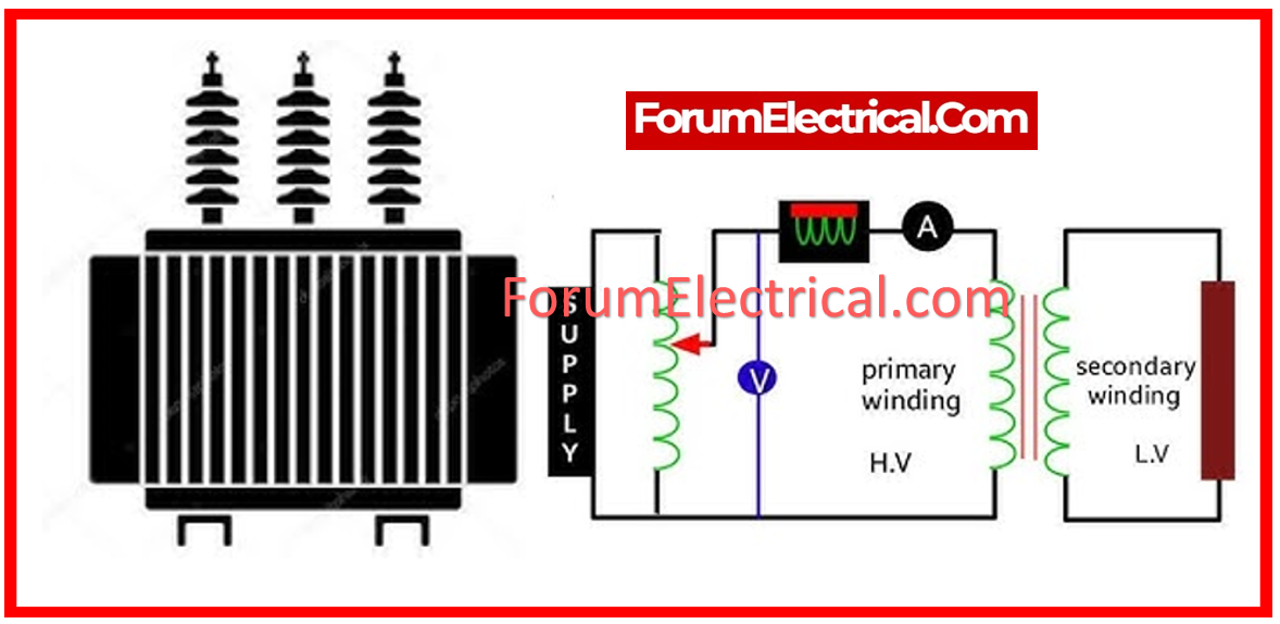
Polarity Test of Transformer
There are two types of transformer polarity tests:
- Additive Polarity of Transformer
- Subtractive Polarity of Transformer
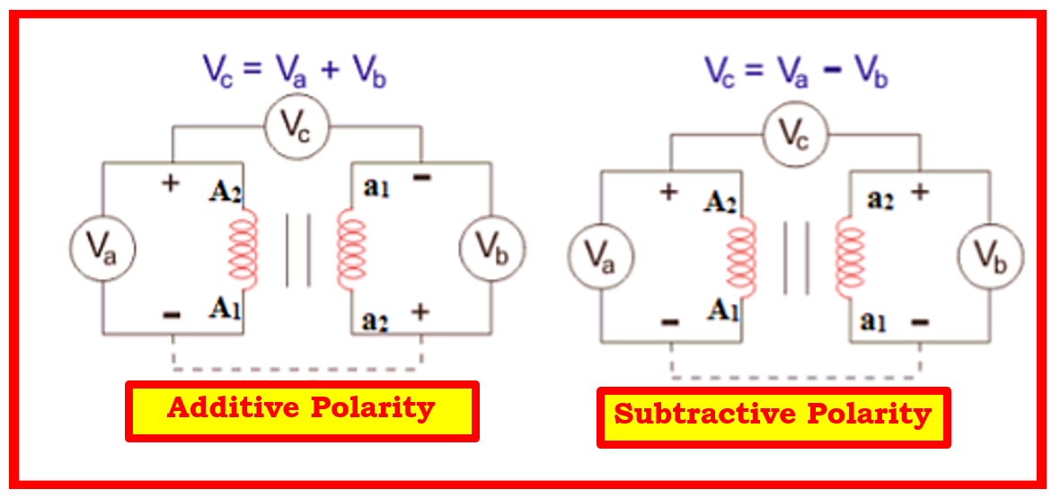
Additive Polarity of Transformer
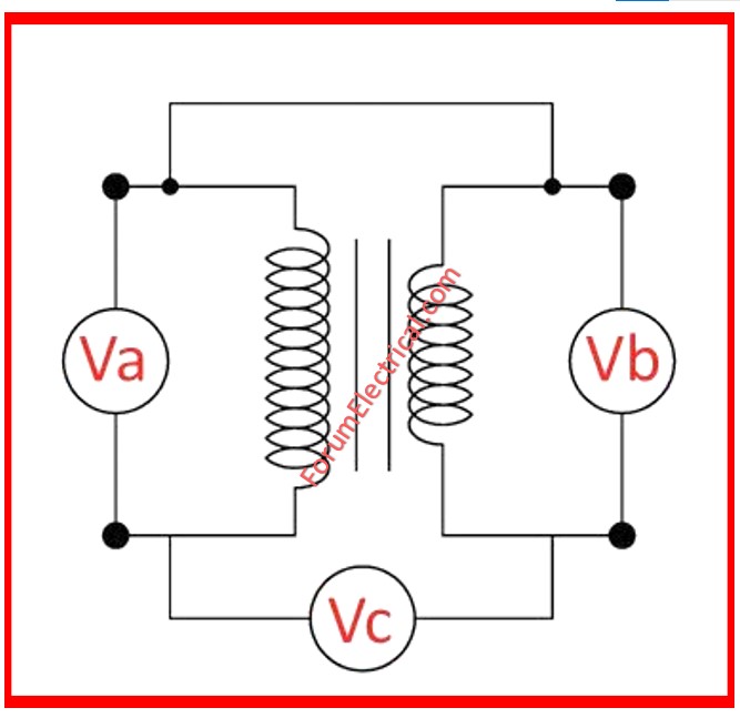
In this polarity, the voltage between the transformer’s primary and secondary coils will be the total of these two voltages.
The voltage is denoted as Vc, whereas the primary coil is Va (high voltage) & the secondary coil is Vb (low voltage).
Small-scale distribution transformers can benefit from additive polarity.
The total voltage for additive polarity can be calculated using the following equation.
Vc = Va + Vb
Subtractive Polarity of Transformer
In this sort of polarity, the voltage between the transformer’s primary and secondary coils is calculated by subtracting the two voltages.
The voltage is denoted as Vc, whereas the primary coil is Va (high voltage) & the secondary coil is Vb (low voltage).
Subtractive polarity is suitable for large-scale transformers. The total voltage for subtractive polarity can be calculated using the following equation.
Vc = Va – Vb
Procedure for Polarity Test of Transformer
- Connect the circuit as shown above, with one voltmeter (Va) across the primary winding and another (Vb) over the secondary winding.
- If available, record the transformer’s ratings and turn ratio.
- We connect a voltmeter (Vc) to the primary & secondary windings.
- We apply voltage to primary side.
- We can determine whether the polarity is additive (or) subtractive by checking the value on the voltmeter (Vc).
If the polarity is additive, then Vc should be the total of Va and Vb.
If the polarity is subtractive, Vc should show the distinction between Va & Vb.
Caution
Make sure that the maximum voltage measured by the voltmeter Vc is greater than the total of Va (primary winding) & Vb (secondary winding), or the sum of Va and Vb will come into contact with it during additive polarity.
Note
If we need additive polarity but only have subtractive, we can remedy it by maintaining one winding and reversing the connections on the other.
The same is true if we require subtractive polarity yet have additive.
ANSI Polarity Rules for Transformers
For additive polarity transformers, the ANSI (American National Standards Institute) rule of thumb states that if the high-voltage (primary) winding leads are connected in one direction (for example, from H1 to H2), the low-voltage (secondary) winding leads will be connected in the same direction (from X1 to X2).
In subtractive polarity transformers, the secondary winding leads will be in the opposite orientation. In practice, it implies that for transformers rated at 200 kVA (or) less & with a voltage rating of 8660 V (or) less, the polarity will usually be additive, with the H1 and X1 terminals on the same side.
For higher ratings & voltages, the polarity will often be subtractive, with the H1 & X1 terminals on opposite sides.
A polarity test on a single-phase transformer determines the relative polarity of the primary & secondary windings, which is required for accurate phase relationships in parallel operations.
This guideline contributes to the proper connection and functioning of transformers in the electrical systems.
What is Dot Polarity?
The dot polarity (dot convention) indicates the polarity of windings in a transformer, demonstrating how voltage is induced.


