When we talk about synchronization, we are referring to the process of minimizing the differences in
- Synchronization Rules
- Voltage Fluctuation
- Synchronization Limits
- Synchronization
- Synchronization of Induction Generators
- Synchronization of Synchronous Machines
- Synchronization Failure
- Failures in Synchronization & Detections
- Detection Methods
- Active Methods
- Passive Methods
- Failure Detection in Power Grid Monitoring
- Voltage,
- Frequency, and
- Phase angle
that exist between the respective phases of the grid supply and the generator output.
Before it can be connected to the grid, an alternating current generator needs to be synced with the distribution system.
If it is not operating at the same frequency as the network, it will not be able to deliver the electric power.
A synchronization process is required to take place before the generator is connected to a grid.
Both manually and automatically operating systems are capable of synchronization.
Synchronization is used to monitor, access, enable, & automatically take control action in order to prevent abnormalities in voltage and frequency. This is done in order to prevent abnormalities.
Synchronization Rules
Voltage Fluctuation
In most cases, there is a fluctuation in voltage on the electricity distribution line whenever a generator synchronizes with a power grid.
It is important that the voltage variation at a point of common coupling does not exceed three percent when the synchronization is taking place.
Synchronization Limits
The limits that let synchronization take place are as follows:
- Phase Angle: +/-20 degrees
- Maximum Voltage Difference: 7%
- Maximum Slip Frequency: 0.44%
Synchronization
The “synch check relay” is the type of relay that must be utilized in order to check the synchronization.
When it comes to induction generators, the utilization of relays is not possible. A synch check relay is utilized for the purpose of accepting as a backup during the process of synchronization and ensuring that a generator will not be connected to a distribution line that is not functioning properly.
Synchronization of Induction Generators
In order to achieve synchronization of induction generators, it is sufficient to simply run them up to the synchronization speed and then link them.
Standard motor controllers will be utilized for the purpose of accomplishing this.
In order to get the generator up to the synchronization speed through mechanical means, power from the turbine shaft will be utilized.
The generated frequency and the number of poles on generators both have an effect on the pace at which the motors rotate.
Synchronization of Synchronous Machines
The output waveform of synchronous generators should be in phase with grid voltage waveform (or) within the parameters that have been defined.
It is imperative that the rate of change of the phase angle across the grid & the machine (representing the generator) falls within the parameters that have been specified.
A variable speed drive (VSD) arrangement is another criterion that must be followed in order to keep the output frequency constant.
Additionally, there must be interconnection protection between the primary generator and the distribution system.
Synchronization Failure
The synchronization circuit may fail to respond to a received input pulse if the received input pulse is shorter than sampling period of synchronizer. This is referred to as a synchronization failure.
When it comes to accurate failure detection and response, standards such as IEEE C37.118 for synchrophasor measurements & IEC 61850 for communication protocols serve a very important or potentially essential function.
It is also possible for the synchronizer to fail to respond during conditions in which the pulse rate of input signal is higher than synchronization rate of synchronizer.
It is possible that the synchronizer itself will fail at times because it will ignore input data.
Each of these conditions has the potential to cause issues if they are not identified and addressed.
The breakdown of power grid synchronization can be attributed to a number of different factors.
Failures in Synchronization & Detections
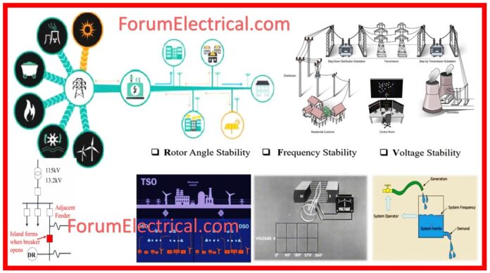
There are several instances in which the generators & some local loads have become separated from the main distribution lines.

Therefore, as a result of this decrease in supply quality, it is possible that it will prohibit devices from automatically reconnecting. It is referred to as islanding.
Because of this, islanding needs to be identified as soon as possible, and the production of power needs to be completed without delay.
Some of the hazards listed below could occur as a result of islanding:
- Earthing is only performed at the sub-station for lines that are generally spread. There is no earthing of the line when the generators and distribution lines are detached from one another. The line voltages may be excessive as a result of this condition.
- There is a possibility that the fault level contribution on the grid to the substation will be lost. This will have an impact on the way protection is conducted on lines that are disseminated. An adequate amount of current might not be created as a result of this are concerned.
- Because of islanding, it is impossible to keep the synchronization going. When the grip makes an effort to reconnect with the distribution line, it is possible that it is not in synchronization at the point where it is supposed to rejoin.
- As a consequence of this, abrupt surges of electricity may occur, which can result in damage to generators, distribution units, and consumer goods.
- Other potential drawbacks associated with islanding include the possibility that the voltage levels will exceed the normal operating limitations, as well as the possibility that the supply quality will be diminished.
Detection Methods
The detection of islanding might be accomplished through either
- Active Methods (or)
- Passive Methods.
Islanding can be detected in an active manner. The active methods will explore the grid by transmitting signals from distribution point of the grid, while the passive methods will check for transitory occurrences on the grid.
Loss of Mains Protection: Loss of Mains Protection, often known as LoM, will be equipped with the capability to detect the disconnection of generators & loads in case an island is created.
There is a possibility that the most widely used approaches for detecting LoM will fail to detect islanding during situations in which the production nearly matches the consumption in island zone.
Non-Detection Zone: NDZ stands for “non-detection zone,” which refers to this blind area. Increasing the tightness of the LoM setting relays is one way to decrease the size of the NDZ.

Active Methods
- Impedance measurement,
- Detection of impedance at a given frequency,
- Slip mode frequency shift,
- Frequency bias, &
- Frequency jump detection methods
are some examples of active methods for islanding detection. Impedance measuring method has the benefit of having a very tiny NDZ for a single inverter, which is a significant advantage.
The approach of slip mode frequency shift is one that is quite simple to put into practice.
This method is highly effective in reducing the possibility of islanding developing when in comparison to the other detecting methods that are accessible.
Passive Methods
Passive method also include frequency jump detection methods.
All PV inverters that are linked to the grid are required to have Over/Under frequency protections techniques and Under/Over voltage protection methods.
These protection methods cause the inverter to stop sending power to utility grid if frequency (or) voltage of the grid at the point of coupling is too high (or) too low.
Additionally serving as anti-islanding measures, these protection methods protect the equipment of consumers and also provide servicing.
Some of the more passive methods for detecting islanding include
- Measurement of voltage harmonics and
- Detection of voltage phase jumps.
It is necessary to implement the Under/Over voltage protection methods as well as the Under/Over frequency methods in addition to the islanding prevention methods.
An aberrant voltage and frequency are produced by a number of different islanding prevention methods.
Both,
- Under/Over Voltage Protection Methods &
- Under/Over Frequency Protection Methods
are examples of low-cost methods that can be utilized for the detection of island effect.
Failure Detection in Power Grid Monitoring
When it comes to power system problems, lighting serves as one of the most common reasons.
- Power Plants,
- Substations,
- Transmission Lines,
- Distribution Feeders, and
- Power Consumers
are the components that make up the overall power system from an electrical standpoint.

The most significant advantage, which includes the achievement of energy conservation, is the identification of synchronization failures between generators and the power grid.
After that, we will be able to prevent the loss of power consumption by temporarily detaching from the devices that consume power.
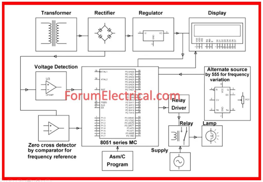
By detecting the difference between the real power and the reactive power, the comparator will be able to determine if there is an under or over voltage or an under or over frequency.
If there is no disruption in the synchronization of the electrical grid, then detectors will result in zero values being generated.
The power sources will be disconnected if any values that are outside of the limitation range are observed, and this will be determined by the
- Under/Over Voltage Readings and
- Under/Over Frequency Readings.


