
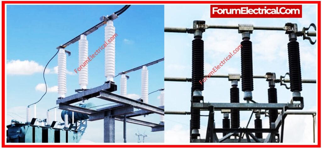
Disconnector and earthing switches are essential components of electrical substations and distribution networks.
- Objective
- Scope
- Equipment Required
- Safety Precautions
- Maintenance Schedule
- Maintenance Procedure
- Visual Inspection
- Mechanical Inspection
- Electrical Tests
- Cleaning
- Functional Testing
- Manual Operation Check
- Motorised (or) Remote Operation Test
- Earthing Switch Verification
- Final Safety Restoration
- Common Issues and Troubleshooting
- Safety Restoration
- Documentation
- Summary
Objective
This preventive maintenance procedure seeks to:
- Ensure the mechanical & electrical integrity of the disconnector and earthing switches.
- Reduce operational downtime.
- Comply with safety and regulatory requirements.
Scope
This maintenance technique relates to:
- Outdoor/indoor air-insulated disconnect switches.
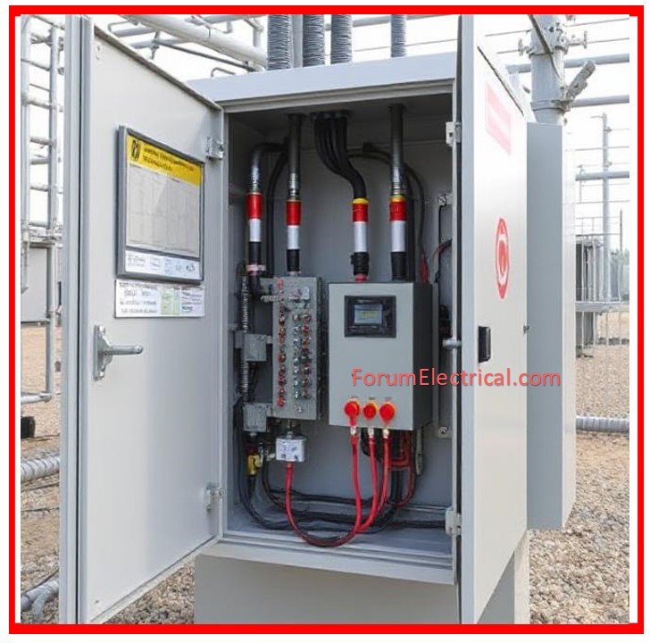
- Disconnect switches can be manual or motor-operated.
- Earthing switches are connected to busbars, breakers, & transformers.
Equipment Required
- Insulation Resistance Tester (Megger)
- Contact Resistance Tester (DLRO)
- Torque wrench and tools.
- Grease the gun with dielectric grease.
- Cleaning agents are non-conductive.
- Infrared Thermal Camera.
Safety Precautions
Before starting any maintenance work:
- De-energize & isolate the circuit.
- Use appropriate lockout/tagout (LOTO) protocols.
- Use the necessary test equipment to confirm zero voltage.
- Wear PPE that meets electrical safety regulations.
Maintenance Schedule
| Equipment Type | Time Schedule |
| Disconnector Switches | Every 6 to 12 months |
| Earthing Switches | Every 12 months |
Maintenance Procedure
Disconnector and earthing switches require preventive maintenance through a planned sequence of visual, mechanical, & electrical inspections to assure dependable performance and safety compliance. This procedure not only minimizes unplanned outages, but it also increases equipment life and lowers the likelihood of arc problems or contact failure.
Visual Inspection
The procedure starts with a thorough visual check for evidence of wear, contamination (or) environmental damage. Inspect all components for obvious deformation, corrosion, loose hardware, and physical damage.
- Check for damage or breakages in the insulating sections.
- Look for corrosion (or) oxidation on terminals & moving joints.
- Check for dirt, dust, oil (or) biological elements (such as bird nests or insects).
- Ensure that identifying plates, warning labels, & nameplates are clean & legible.
This inspection should take place while the equipment is de-energized and properly isolated.
Mechanical Inspection
Mechanical durability is important for the safe operation of disconnector & earthing switches.
After establishing that the equipment is isolated & safe to operate on, run a manual test of the switch through its entire range.
- Check for any stiffness, mechanical restriction, or misalignment.
- Check that the moving contacts are accurately aligned with the fixed jaws & that contact engagement is complete and secure.
- Tighten all nuts and connections with a torque wrench to the manufacturer’s specifications.
- Apply dielectric-grade lubricant to the hinges, bearings & other moving parts as needed, avoiding live contact areas.
- Inspect the spring mechanism (if present) for proper tension and replace any worn parts.
This phase ensures that mechanical motion is smooth and that the gadget can operate without jamming (or) partial contact.
Electrical Tests
Electrical testing ensure the reliability and performance of current-carrying paths & insulating systems. These tests should be performed using calibrated instruments.
Contact Resistance Measurement: Utilize a digital low-resistance ohmmeter (DLRO) to determine contact resistance across each pole. Values should normally be fewer than 100 microohms.
Insulation Resistance Test: Using a 1 kV (or) 5 kV insulation tester, measure the resistance between each phase & ground. A number exceeding 1 GΩ is often regarded acceptable.
Continuity Check (for Earthing Switches): When the switch is closed, make that there is a low-resistance path to ground.
Optional Thermographic Scan: Under live load (if permitted), use infrared thermography to detect hot spots or aberrant heating at terminals and contact points.
These findings should be documented for trend analysis as well as the detection of performance declining condition.

Cleaning
Cleaning is essential to avoid insulation breakdown and tracking. Perform this after the visual and mechanical examinations, but before re-energizing.
- Clean the insulators with dry, lint-free towels or isopropyl alcohol.
- Remove oil, oxidation & other residues from the metal contact surfaces with fine-grade abrasive pads or an approved contact cleaner.
- Avoid using water (or) any conductive cleaning fluids.
- Clean all moving components after lubrication to remove any extra grease or dirt.
- A clean switch assembly provides excellent dielectric performance and operating safety.
Functional Testing
After maintenance, functional testing is required to ensure that the switch performs correctly and safely in both manual and motorized modes (if applicable).
Manual Operation Check
- Manually operate the disconnect & earthing switches from open to closed, and vice versa. The motion should be fluid, with no binding or undue resistance.
- Ensure that the contacts are fully engaged and disengaged during operation.
- Listen & sense for a solid locking action or “snap” at the end positions.
- Check if interlocks (mechanical or electrical) are working to prevent inappropriate operation.
Motorised (or) Remote Operation Test
To ensure dependable actuator response & auxiliary signaling, operate motorized switches both locally and remotely (if SCADA-connected).
- Check motor performance for strange noises, delays, or failures.
- Check that the position indications and feedback signals reflect the physical condition of the switch.
- To avoid hazardous commands, test the local and remote interlocking functions.
- Check that all auxiliary signaling contacts are working properly.
Earthing Switch Verification
- Operate the earthing switch & ensure that it engages smoothly & makes a strong connection to ground.
- Measure continuity to provide a low-resistance path to the earthing grid.
- Visually confirm that grounding blade is completely seated.
- Check the interlocks to ensure the earthing switch cannot be closed while the circuit is live.

Final Safety Restoration
After all tests are finished:
- Ensure that all covers, panels, & obstacles are securely replaced.
- Confirm the switch’s final position (open/closed/earthed) as per system specifications.
- Remove lockout/tagout devices only after ensuring safety.
- Update the maintenance logs with the test results, observations, & corrective actions taken.
Common Issues and Troubleshooting
| Problem (Issue) | Causes | Solution |
| High contact resistance | Worn (or) pitted contacts | Clean (or) replace contacts |
| Difficulty in the manual operation | Lack of lubrication, misalignment | Lubricate & re-align mechanism |
| No continuity in the earthing path | Loose connection (or) corrosion | Tighten (or) replace terminals |
Safety Restoration
- Confirm that the switch is in the correct position (open, closed or earthed).
- Remove all temporary test links.
- Restore all covers, barriers, & interlocks.
- Remove LOTO tags only when the system has been completely cleared.
Documentation
All maintenance activities must be fully documented, including the date, location, personnel, & equipment identification.
Key observations, test results, abnormalities, & corrective measures should all be well documented.
Proper documentation ensures traceability, enables predictive maintenance, and meets regulatory requirements.
Summary
Routine preventative maintenance of disconnector & earthing switches is critical for electrical system dependability and worker safety.
A thorough inspection and testing procedure assist in the early detection of potential difficulties and ensures that the power system operates continuously.


