
Preventive maintenance is essential for the longevity and efficiency of high-tension (HT) motors, which are commonly used in industrial & commercial applications. Here are some guidelines for planning an effective HT motor preventive maintenance schedule.
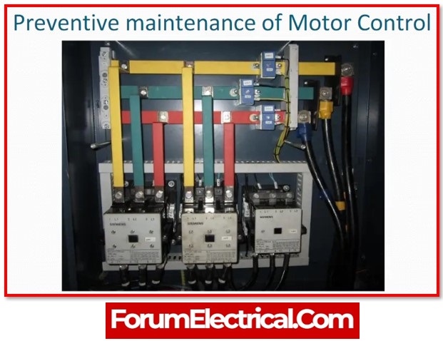
HT Motor Preventive Maintenance
This form of maintenance must be carried out under the supervision of a competent Electrical Technician (or) Maintenance Supervisor, who is responsible for ensuring that the procedure is carried out accurately, safely, and effectively, without causing unforeseen production deferral.
Coordinate with the local Control Room operator to ensure that the equipment control supply is disconnected from the panel.
Required Test Equipment
- Multi-meter
- Relay test kit
- A set of electrical tools
- Megger

Spare Parts
Not Needed (or) Not Available
Safety
- Obtain a work permit from the appropriate governing body.
- Ensure that the circuit is dead & that all static energy has been dissipated.
- To the specified authority, issue an electrical isolation certificate.
- Make use of personal protection equipment.
- The Control Room must be notified that work is being done on the motor.
- Ensure that suitable PPE (helmet, gloves, goggles, ear plug/earmuff, dust mask, high visibility clothing, and safety footwear, where applicable) is used and that it meets the fundamental safety requirements.
- Make sure that all of the precautions and protocols for safety are followed.
- Before starting the task, hold a toolbox meeting.
- The toolbox meeting should clarify the assignment step and the risk associated in carrying it out.
Before The Test
Brief the operator on the scope of work and assist in implementing safety measures such as PTW, vigilance, process reading interruption & manning requirements, risk and its mitigation. Confirm with the operator that safety precautions are in place. Obtain the operator’s signature on the PTW (Permit to Work).

Procedure
Motor
- Externally clean the motor.
- Clean and examine cooling fan fins for damage, and replace if necessary.
- Check lubricating systems and lubricate the bearings as needed.
Terminal Box
- The interior of the terminal box should be cleaned.
- Visually inspect the terminal box seal (or) gasket condition and replace if necessary.
- Examine the terminal connection Insulation and crack/damage insulators
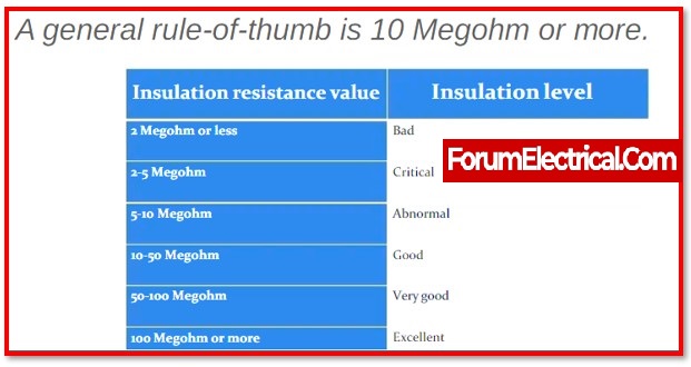
- Carry out the Motor Insulation Resistance Test using Cable.
- Carry out the motor winding impedance test using Cable.
- To inspect the motor, do an MCSA (Motor Current Signature Analysis) test and examine
- Power Analysis
- Air Gap
- Stator Fault
- Rotor Fault
- If applicable, ensure that the proof Certificate is revalidated in accordance with IEC standards
- Check the heater’s tightness and condition.
- Check the tightness of the motor power cable terminal connection.
- Examine the motor’s earth connection.

Motor Feeder
- Ensure that the motor feeder & its internal components are clean.
- Check the circuit breaker functional test.
- Examine the function of the panel anti-condensation heater.
- Check the feeder side power & the tightness of the control connection.
- Examine the condition and operation of the panel selector switches.
- Examine and replace the blown indicator lamp on the panel.
- Examine the feeder earth connection.
- Check the space heater’s functionality.
Protection Relay
Test & calibrate the motor protection according to manufacturer recommendations, and record test results.
- Over current protection
- Earth fault protection
- Negative sequence protection
- Thermal overload protection
- Locked rotor protection
- Differential protection
- Under / Over voltage protection
- Under current protection
- Trip circuit supervision
- Auxiliary relays
This activity requires a certified protection engineer and secondary injection equipment.
Determine that the unit is completely isolated, earthed/discharged, and safe to work on.
The selected bus segment should be used.
Confirm the qualified protection engineer completing function tests on the protective relay equipment, utilizing the exact settings applicable to each individual relay.
Manual Switch
- Clean the switch & its components.
- Examine the terminal connection for tightness.
- Examine the knob if any cracks or damage.
- If necessary, replace.
- Check the switch’s continuity.
- Check that all cable connections are tight & in good working order.
- Examine the earthing connection for integrity.
Push Button
- Clean the switch & its components.
- Examine the terminal connection for tightness.
- Examine the knob for cracks or damage and replace if necessary.
- Check the switch’s continuity.
- Check that all cable connections are tight & in good working order.
- Examine the earthing connection for integrity.
De-Isolation
- Make sure that the electrical isolation has been successfully removed.
Close-Out
- Return the work permit and close it.
- Keep track of all observations and actual work completed, including spares.
- Collect any leftover objects to ensure proper housekeeping.
- Make the appropriate arrangements to dispose of utilized materials in accordance with environmental regulations.
- Any deviations should be reported for corrective action.
- Enter observations and history into SAP for line supervisor performance analysis.
- This is going to be in beneficial for reference.
- Complete the work order.
Motor Checklist
| S. No | Activities | Remarks |
| 1 | Externally clean the motor. | |
| 2 | Examine the terminal connection for tightness. | |
| 3 | With a cable, test the motor’s insulating resistance. | |
| 4 | Examine the motor’s polarization index. | |
| 5 | Conduct a motor MCSA analysis test. | |
| 6 | Examine the cooling fan for any signs of damage. | |
| 7 | Examine the space heater | |
| 8 | Examine the Earthing connection | |
| 9 | Examine the lubrication of the bearings. |
Feeder Checklist
| S. No | Activities | Remarks |
| 1 | Clean the inner and exterior of the panel. | |
| 2 | Inspect the terminal connection for tightness. | |
| 3 | Examine the operation of the panel cooling fan. | |
| 4 | Examine the operation of the panel heater. | |
| 5 | Examine the operation of the pushbutton and selector switch. | |
| 6 | Replace any blown indicator lamps. | |
| 7 | Check the circuit breaker’s function. | |
| 8 | Examine the Earthing connection | |
| 9 | Examine the function of the Protection Relays. |

 motors are intended to increase the motor's lifespan and avoid costly downtime. This post discusses several critical preventive maintenance tasks.)