
Slip Power Recovery is one way for managing the speed of an induction motor.
This method is sometimes referred to as Static Scherbius Drive.
During low-speed operation, the rotor resistance management approach wastes slip power in the rotor circuit due to I2R losses.
The efficiency is also diminished. Slip power from rotor circuit may be recovered & sent back into the alternating current source for use outside the motor.
Thus, the total effectiveness of the driving system can be improved.
The essential idea behind slip power recovery is to link an external source of EMF of slip frequency of rotor circuit.
The slip energy recovery method allows for speed control of the slip ring induction motor beneath its synchronous speed.
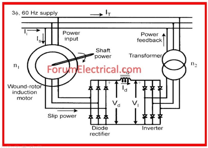
A diode bridge converts a portion of the rotor’s AC power (slip power) into direct current.
The smoothing reactor is designed to smooth the rectified current. The rectifier’s output is then linked to the inverter’s DC terminals.
The inverter converts DC power to AC power and sends it back into the AC source. The inverter is controlled rectifier that operates in inversion mode.
This form of speed control is utilized in the large power applications when varying speed over a wide range requires a significant amount of slip power.
What is Slip Speed?
Slip speed is the acceleration rate of the induction motor operation.
Slip speed is the difference between the synchronous speed of the rotor and its actual speed.
The slip speed reveals the relative rotor speed in relation to the field speed.
Slip power is a component of the air-gap power not turned into mechanical power. It is denoted as spg.
When
s=slip,
pg= air-gap
Slip power recovery is the process by which air gap power squandered in a rotor is returned to the supply mains.
How is Slip Power Recovered?
The speed control of the slip ring induction motor below its synchronous speed is given by the slip energy recovery method.
A diode bridge converts some of rotor alternating power (AC) power (slip power) into DC. Inverts the DC power to the AC power & feeds it back to the AC source.
Mostly, this technique is utilized for control of induction motor speed.
Waste of slip power in a rotor circuit causes low efficiency in the speed control in induction motors.
Recovery techniques help to control the induction motor speed, so preventing slip power loss.
Classification of Slip Power
There two categories for the slip power.
- Static Scherbius system
- Static Kramer system
1). Static Scherbius Drive System
This system has a feedback path, which means that any wasted slip power is returned back into the AC mains supply.
The static scherbius system has two types.
- Conventional Scherbius System
- Static Scherbius System
Conventional Scherbius System
In this system, the recovery mechanism is implemented through a feedback path. The output of a three-phase induction motor is connected to a DC motor by coupling them.
The mechanical power input of the DC motor is transformed into electrical power and fed to an induction generator before returning to the mains.
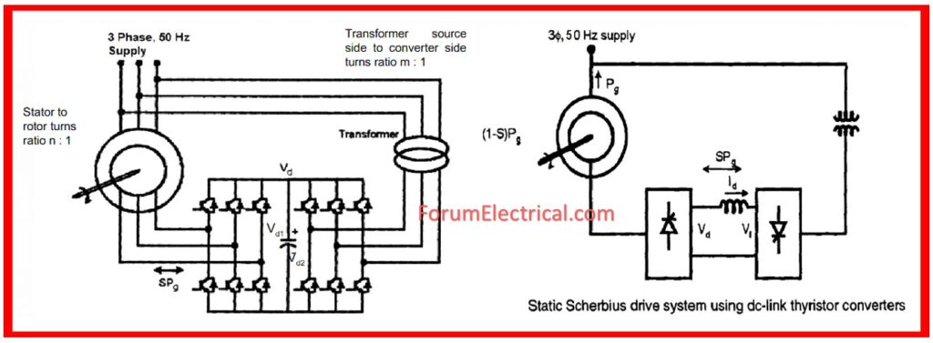
Static Scherbius System
This system behaves similarly to traditional systems, with the exception that it includes a diode bridge rectifier as well as a thyristor bridge inverter.
This is also called as a sub synchronous cascade drive.
When an induction motor operates at slip frequency, the rotor slip power is rectified by a diode.
The rectifier’s output is fed to the inverter three phase bridge, which then feeds the output back to the supply lines via the transformer.
We can achieve subs synchronous and super synchronous speeds using static scherbius drives.
Static scherbius drives allow for bidirectional power flow, with positive and negative injected voltages that can be in phase with (or) opposing the rotor current. As an outcome, a broader range of operating conditions is feasible.
2). Static Kramer Drive System
The static Kramer-drive is the technique of injecting opposite-phase voltage in rotor circuit to control the speed of an induction motor.
The injected voltage raises the rotor’s resistance, hence regulates the motor’s speed. Changing injected voltage helps to manage an induction motor speed and resistance.
The static Kramer-drive supplies back to the line AC power from slip power of an induction motor. In addition transformed into mechanical power, the slip power is the air gap power across the stator & the rotor of an induction motor. The power is so being wasted.
Driven back into the main supply, the stationary Kramer feeds wasted power. This approach is only relevant when the drive’s speed is smaller than synchronous speed.
Advantages of Slip Power Recovery System
- The chopper method of the speed control for SRM wastes slip power in the external resistance, reducing efficiency.
- Rather than losing slip power, numerous techniques for speed management of slip ring induction motors can be used to recover it.
- Slip power may be recovered & fed back into the supply. So overall efficiency improved.
Difference between Static Kramer System and Static Scherbius System
Static Kramer System vs Static Scherbius System
| Parameters | Static Kramer System | Static Scherbius System |
| Working Principle | Converts slip power to DC and returns it to the source via a DC connection. | Slip power is converted into alternating current and sent back into the supply using an inverter. |
| Power Flow | Partial slip power recovery using a DC drive. | A complete slip power recovery utilizing an inverter. |
| Components Used | Rectifier, DC motor, and thyristor converter. | Rectifiers, inverters, transformers, and thyristor converters. |
| Efficiency | DC conversion losses reduce efficiency compared to Scherbius. | More efficient since it returns power straight to the alternating current supply. |
| Speed Control | Speed control is accomplished by altering the DC link voltage. | The inverter output can be adjusted to control the speed. |
| Reversibility | Only works in sub synchronous mode (below synchronous speed). | It operates in both sub-synchronous & super-synchronous modes (below & above synchronous speed). |
| Cost & Complexity | It’s simpler and less expensive because it uses a direct current drive. | The inverter system makes things more complicated & costly. |
| Applications | Used in pumps, fans, and compressors where sub synchronous operation is required. | Used in wind turbines, huge industrial motors, & applications that require both sub- & super-synchronous operation. |


 in induction motors, including its operating principles, benefits, and major technologies such as Static Kramer and Static Scherbius systems for effective speed management and energy savings.)