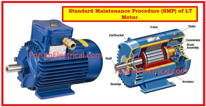
A Standard Maintenance Procedure (SMP) helps to perform maintenance tasks. Industry SMPs must be accurate to avoid maintenance errors. Because inadequate data can be worse than none. False data can cause misanalysis and results. Preventing this requires a well-written data collection procedure.
The SMP provides extensive maintenance instructions. The work must be done according to SMP. SMPs cover all repetitive work that workers, contractors, and operators can do.
Scope
Preventative maintenance of the LT motor.
Objective
Ensure the motor’s health and perform preventive checks to avoid the equipment from failing during operation.
Location
High temperature area.
Tools Required
- LT Megger,
- Multimeter,
- Screwdriver,
- Spanner set,
- Insulation tape,
- Air blower,
- Cotton waste, and
- Cleaning brush
are all required.
Safety PPE
- Proper isolation.
- Shut down with tag out (LOTO).
- Work permit will be taken.
- Barricade the Area that has to be maintained.
- Use proper tools and personal protective equipment.
Hazards
- Fall objects on your head.
- Due to the use of an incorrect tool, tools slippage and sharp edges of instruments or frames.
- Due to high temperatures skin burns problem.
Risk
- Human Injury
Manpower Requirements
02/03 – Number of Manpower
Responsibility
Initiator
One Electrical Engineer
- The engineer is in charge of establishing and restoring electrical isolations for non-process equipment jobs.
- The area engineer will plan, supervise, maintain records, and brief on safety considerations.
Executer
Two Electrical Technicians
- The authorized electrical person takes responsibility for safe electrical isolation and restoration, including filling up and signing the “electrical isolation tag”.
Time Duration
3 hours.
Scope of SMP
Standard Maintenance Procedure (SMP) is applicable to LT motors.
Step-by-Step Procedure for Motor Preventive Maintenance
Motor Maintenance
- Before commencing the work, ensure SCC has been issued by the operation shift In-charge. Isolate the motor and tag out the breaker/feeder before starting work.
- Remove and inspect the canopy. Repair as needed.
- Clean dust from the motor body & terminal box with a portable electric blower and brush.
- Remove the terminal box cover to discharge the power cable.
- Clean grease cap on motor DE side if accessible.
- Visually inspect the gland plate and power cable glands and use glass putty to plug any gaps found.
- Ensure double earthing of the motor body.
- Ensure correct glanding of the motor cables & plug any holes.
- Inspect the motor/space heater terminal box. Measure the resistance of the space heater.
- Visually inspect the driving end (DE) side end cover.
- Visually inspect the cooling fan cover, cir-clip, & grease nipples.
- Cleaning the cooling fan as needed, and replace it if it is cracked or broken.
- Open the terminal short links and record the motor’s IR value. (more than one mega-ohm):
Note: Before opening the cable connection, write down the connection sequence.
a). U-E,
b). V-E.
c). W-E,
d). U-V
e). U-W
f). V-W.
- Check the winding resistance of the motor (U1-U2/V1-V2/W1-W2).(Must be balanced).
- Reconnect and tighten short link connections.
- Close the terminal box cover and tighten bolts.
- Seal the cover with AL tape.
- Clean the work area of any leftovers and debris.
Preventive Maintenance of LCS
- Prior to starting work, identify the relevant Local Control Station (LCS) with the field engineer.
- Ensure the motor feeder is properly disconnected and labeled out.
- Clean the LCS cabinet using a brush and cotton towel.
- Use a screwdriver to check control wire tightness.
- Check for mechanical damage to push buttons, indicators, and ammeters and replace as needed.
- Use a multimeter to check the function of the NO and NC push buttons.
- Paint the LCS cabinet if necessary.
- Close cabinet and tighten bolts.
- Seal the LCS cover using AL tape.
- After conclusion of work, return the PTW to the Shift In-Charge and acquire clearance for charging.
Preventive Maintenance of Feeder/ACB
- Use a portable electric blower & brush to clean dust within the feeder.
- Tighten control and power cables.
- Checking the healthiness of the male female connector (jaw).
- Determine the resistance of the closing and tripping coils in case of ACB.
- Check the health of the arc chute assembly in case of ACB.
Precaution Measures
- Isolation requires a correctly filled “Electrical Isolation Tag”.
- Restoration will be done only if the complete LOTO key is returned and the permit is cancelled.
- When restoring power, check that the isolation tag number on the stub matches the tag on the panel.
- For VFD-operated motors, work should start after 15 minutes of electrical isolation to allow time for capacitor discharge.
Do not remove the “Electrical Isolation Tag” from the equipment during maintenance operations.


