What is Static Kramer Drive?
The technique of controlling the speed of an induction motor through the injection of opposite phase voltage into the rotor circuit is known as the Static Kramer-drive.
The current injected voltage increased the rotor impedance and thereby controlled the speed of the motor.
The rate of an induction motor and its resistance is altered depending on the voltage that is injected.
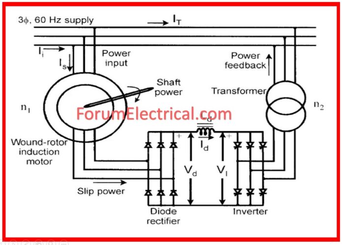
Induction motor slip power is converted to and supplied back to line AC power by the Static Kramer drive.
The slip power refers to the real air gap power of an induction motor which is not utilized in providing mechanical energy.
Therefore the power is being wasted. It is necessary to supply the power that is required for the static Kramer drives in a static manner, and any power that is wasted is recycled back into the main supply.
This method only works when the drive is lower than synchronous.
Construction of Static Kramer Drive
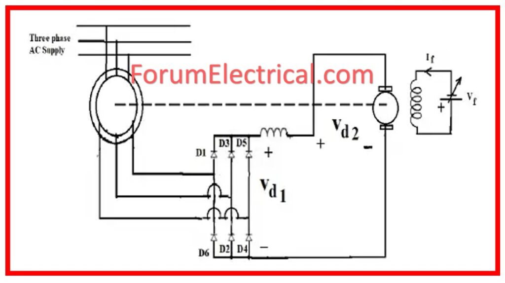
The Static Kramer drive system, which is comprised of a variable-speed drive system, is outfitted with a slip ring induction motor as well as a rectifier-fed direct current motor.
Slip Ring: The slip power recoveries is provided through the rectifier and the auxiliary DC Motor.
Torque offered to load is sum torque of produced separately by induction and DC motors. Rapidly speeds are regulated by stabilizing field current of DC motor.
Diode: If a larger speed range is needed, the diode bridge shall be replaced by a thyristor bridge. Control over speed can now be augmented to talking to standstill, if required.
Because when a Static Kramer Drive system has no line-commutated inverter present, it gives rise to lower reactive power and small values of harmonic components of currents as compared to a Static Scherbius system.
However, unlike brushes & commutator of an auxiliary DC motor, it has a large moment of inertia, which is a disadvantage. Additionally, it has maintenance issues that are difficult to work effectively.
In order to realize the speed control of the induction motor, one has to analyze the operation of the inverter which converts the dc power to variable frequency ac power.
Before we get into this, we will first talk about the phase-control scheme that will be used to manage the voltage of the stator.
Working of Static Kramer Drive
The rotor slip power is rectified by a diode bridge which gives direct DC output voltage for further processing.
Currently, this direct current (DC) power is being delivered to the direct current (DC) motor, which is mechanically attached to an induction motor.
As it has been found the torque supplied to the load is the total sum of the torque produced by the induction motor and the DC motor drive.

The function of Vd1 & Vd2 with speed of two values of DC motor field current. It is therefore possible to acquire the steady state operation of drive when Vd1 equals Vd2, which indicates that the drive is in the A & B positions for field current If1 & If2.
Only speeds less than half the synchronous speed can be controlled.
In case where the large range speed is required the diode bridge is in turn replaced by thyristor bridge.
The level of dependence between Vd1 and speed may be changed by changing the firing angle of the thyristor amplifier.
Thus, velocity management has become possible up to cover stillness.
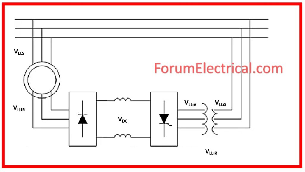
The diode rectifier ensures that the voltage at the slip rings has to be in phase with the rotor currents. The voltage levels of the slip ring is dependent with the DC link voltage which is dependent with the inverter connected to the ac supply. In the diagram above as well as in the analysis shown, the one used is thyristor converter kind of an inverter. However, a pulse width modulation (PWM) inverter is a further selection.
Simple Analysis of Static Kramer Drive
This simple analysis of the Static Kramer drive reveals the operation of the drive as explained in the paper. It fails to consider voltage drops in the actual drive as well as possible commutation overlap in the diode rectifier.

The supplied voltage indicated is the voltage across the diode rectifier input.
VLLiR = √3 (Vi/aeff)
Where
VLLiR – Line-to-Line Voltage
Vi – Input Voltage
aeff – Diode Rectifier Input Voltage
and the dc link voltage can be determined from the diode input line-line voltage as
VDC = (3√2/Π) VLLiR
Where
VDC = DC Link Voltage
With respect to the thyristor converter only it can be said that this circuit corresponds to the thyristor rectifier under inversion and the DC link voltage depends on line-line inverter voltage as
VDC = – (3√2/Π) VLLinv cosα = 3√2/Π) VLLinv |cosα|
Substituting the above formulas yields rotor voltage:
Vi = (aeff/√3) VLLinv|cosα|
Vi = (aeff/√3) (Niv/NLine) VLLS|cosα|
By using this simplified analysis in conjunction with the slip energy recovery torque equations it is possible to determine the thyristor firing angle for the production of a particular torque at a particular speed. If required, further analysis can be done by performing the above process again with inclusion of device voltages and commutation overlap.
Torque-Speed Characteristics of Static Kramer Drive
The torque speed curve for a motor driven by a static Kramer drive does not provide negative torque once the speed reaches the no-load speed because of the slip ring voltage produced by a diode bridge.
If the slip is beyond a certain limit for a given injected voltage, the voltage couple in the rotor circuit by stator will be less than that of the DC link voltage.
Consequently, there will be no current in the rotor and there will be no torque yielded.


