- What is Switch?
- Characteristics of Switches
- Mechanical Switches
- Types of Mechanical Switches
- 1). SPST – Single Pole Single Throw Switch
- 2). SPDT – Single Pole Double Throw Switch
- 3). DPST – Double Pole Single Throw Switch
- 4). DPDT – Double Pole Double Throw Switch
- 5). Pressure Switch
- 6). Toggle Switch
- 7). Limit Switch
- 8). Float Switches
- 9). Flow Switches
- 10). Push Button Switch
- 11). Temperature Switches
- 12). Joystick Switch
- 13). Rotary Switches
- Electronic Switches
- Types of Electronic Switches
- 1). Bipolar Transistors
- 2). MOSFET
- 3). IGBT
- 4). TRIAC
- 5). DIAC
- 6). SCR
- 7). Gate Turn-Off Thyristor
- 8). Power Diode
What is Switch?
A switch is an electrical component that can create or break an electrical circuit automatically (or) manually.
The switch is mostly used with an ON (open) & OFF (closed) mechanism. Many circuits contain switches that affect how the circuit functions or activate certain circuit properties.
Characteristics of Switches
- Application determines switch type: toggle, push-button, rotary, flow, or limit switch.
- Number of circuits the switch can control (poles) & positions or outputs it can link to (throws).
- Durability and conductivity depend on contact material, usually silver, gold, or copper.
- The switch’s maximum safe current and voltage.
- The force needed to engage (or) toggle the switch.
- The number of times a switch can be activated before failure.
- The number of electrical load operations a switch can accomplish before failure.
- Panel-mount, surface-mount, (or) through-hole switch installation.
- Waterproofing, dustproofing, and severe temperature resistance are examples of environmental adaptability.
- Physical size and design affect usability and circuit or device integration.
In general, there are 2 types of switches used in an electrical circuit:
- Mechanical switches and
- Electronic switches
Mechanical Switches
Mechanical switches are classified according to the connections they created.
- Pole and
- Throw
are two important components that determine the types of connections made by a switch.
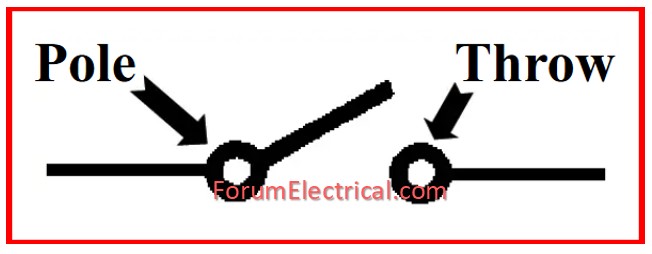
Pole: Poles indicate how many circuits the switch controls. A single pole (SP) switch regulates a single electrical circuit. A double pole (DP) switch regulates two independent circuits. The number of “poles” represents the number of different circuits controlled by a switch.
Throw: The number of throws determines how many possible output connections each switch pole can make to its input. A single-throw (ST) switch is a basic on/off switch. When the switch is turned on, current flows between its two terminals.
When the switch is turned OFF, the terminals are not connected, so no current flows. The number of “throws” represents the number of different positions that switch may adopt.
A single-throw switch features only one pair of contacts, which can be closed or opened. A double-throw switch can link to two other contacts, a triple-throw switch to three, etc.
Types of Mechanical Switches
The basic types of switches are
1). SPST- Single Pole Single Throw Switch,
2). SPDT – Single Pole Double Throw Switch,
3). DPST – Double Pole Single Throw Switch,
4). DPDT – Double Pole Double Throw Switch,
5). Pressure Switches,
6). Toggle Switch,
7). Limit Switch,
8). Float Switches,
9). Flow Switches,
11). Temperature Switches,
12). Joystick Switch,
13). Rotary Switches.
These are briefly covered below:
1). SPST – Single Pole Single Throw Switch
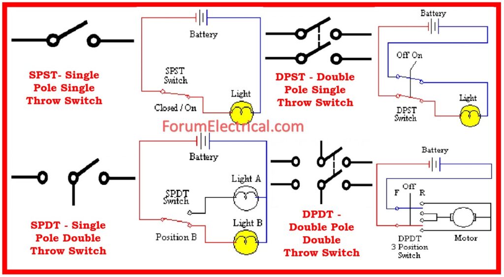
- The Single Pole Single Throw (SPST) is a simple on/off switch that connects or disconnects two terminals.
- The SPST switch switches a circuit’s power supply.
- These switches are toggle switches.
- This switch has input and output connections.
- The basic light switch diagram shows that it controls one wire (pole) & makes one connection (throw).
- This is an on/off switch; when the switch is closed or turned on, current flows pass the terminals, and the bulb in the circuit glows.
- Once the switch is either open or closed, no current flows through the circuit.
2). SPDT – Single Pole Double Throw Switch
- There are two output and one input terminals on this switch.
- This means it has two ON and one OFF positions.
- In most circuits, these switches serve as a changeover point, connecting the input to one of two output options.
- The typically closed contact is connected to input by default, while the normally open contact is connected during ON operation.
3). DPST – Double Pole Single Throw Switch
- This switch has 4 terminals 2 input contacts & 2 output contacts.
- It acts as if 2 independent SPST configurations are working simultaneously.
- It only has one ON state, but it can activate both contacts at the same time, connecting each input contact to the matching output contact.
- In the OFF position, both switches are open.
- This switch controls two circuits simultaneously.
- These switches can also have normally open (or) closed contacts.
4). DPDT – Double Pole Double Throw Switch
- Switch with Dual-ON/OFF with two ON positions. & 6 terminals: 2 input and 4 output connections.
- It behaves like two different SPDT configurations that operate concurrently.
- One position connects 2 input contacts to the same output contacts, while another connects them to opposing output contacts.
5). Pressure Switch
- In industrial environments, these switches are frequently used to check the pressure in pneumatic and hydraulic systems.
- They are categorized as piston-type, metal bellow, and diaphragm-operated pressure switches based on pressure range that monitor.
- Each type of pressure sensing element triggers a succession of single-pole or double-pole connections.
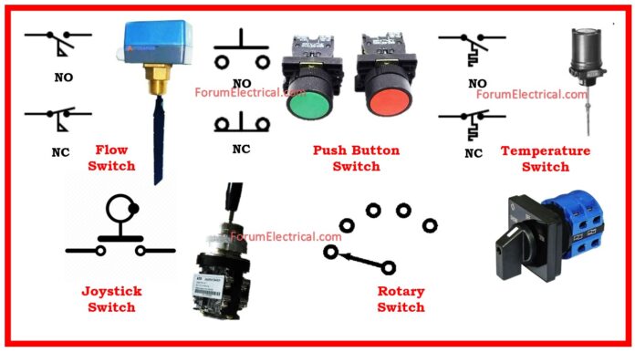
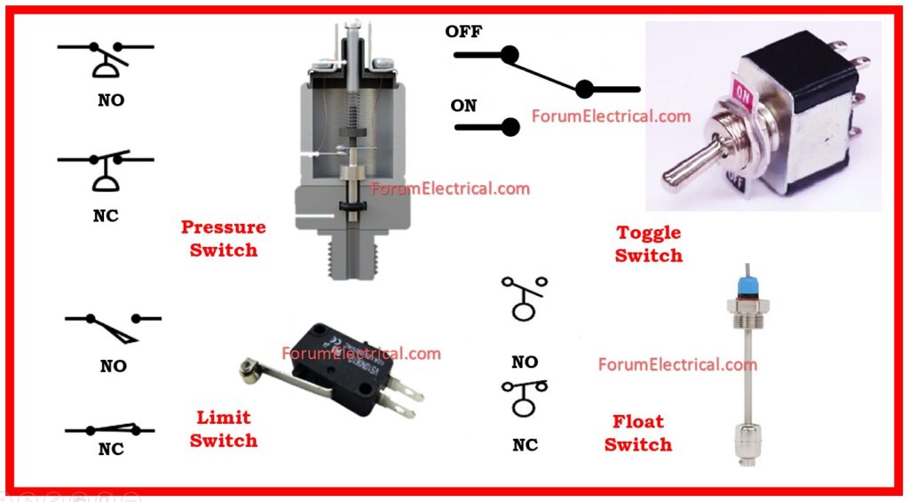
- These switches are represented by a half-circle with the flat portion attached to a line.
- They can be set up as switches that are normally closed or normally open.
6). Toggle Switch
- A handle, lever, or rocking mechanism controls a toggle switch. It is commonly used to regulate lights.
- These switches’ levers are often adjustable in several settings, including SPDT, SPST, DPST, & DPDT.
- They can take high currents (up to 10 A) or low currents.
- Toggle switches exist in a variety of ratings, sizes, & styles to suit diverse applications.
- The ON position can be any lever position, however the downward position is typically regarded ON or closed.
7). Limit Switch
- They are intended to function based on presence (or) absence of components, or the movement of equipment, rather than human hand manipulation.
- These switches employ a bumper-type arm that responds when a component makes contact with it. This causes a shift in position of switch contacts.
8). Float Switches
- Float switches are mostly used to regulate DC & AC motor pumps based on the water or liquid in a sump or tank.
- This switch activates when a tank float rises or falls, depending on water level.
- Electrical contacts open or close as a result of the rod (or) chain assembly & counterweight floating. The mercury bulb type switch, which is another sort of float switch, is devoid of any float rod or chain configuration.
- This lightbulb has mercury contacts, thus when liquid level changes, so does the condition of the contacts.
- These float switches come in two varieties: normally closed and normally open.
9). Flow Switches
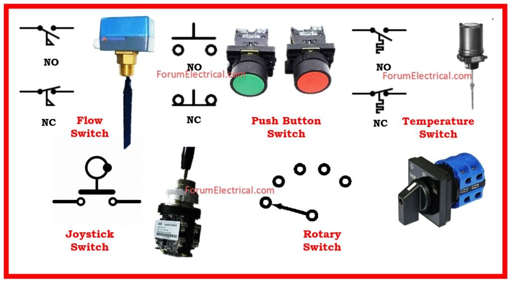
- These are mostly employed to identify the flow of air or liquid through a duct or pipe. A snap-action is used to produce the air flow switch, often known as a micro switch.
- A metal arm has this micro switch fastened to it. A thin piece of metal or plastic is attached to this metal arm.
- The metal arm moves when a lot of air flows through the plastic or metal component, which in turn activates the switch’s contacts.
- A paddle that is put across the liquid flow in a pipe is a feature of liquid flow switches. The contacts’ positions are altered as force is applied to the paddle as liquid passes through the pipe.
- The switch sign used for both liquid and air flow is depicted in the above illustration. The paddle that detects the movement or flow of liquid is indicated by the flag symbol on switch.
- Additionally, these switches have configurations of the normally open (or) normally closed types.
10). Push Button Switch
- It is a transient contact switch that connects or disconnects when pressure is applied (or) the button is pressed.
- Typically, this pressure is given by a button pressed with a finger.
- When the pressure is removed, this button returns to its usual position.
- The internal spring mechanism controls the 2 states (pressed & released) of a push button.
- It consists of stationary & movable contacts, with stationary contacts linked in series with circuit to be switched and movable contacts attached via a push button.
- Push buttons are classed into three types: typically open, normally closed, and double action push buttons, as illustrated in the figure above.
- Double-acting push buttons are typically used to operate two electrical circuits.
11). Temperature Switches
- The bimetallic strip, which uses the principle of the thermal expansion, is the most widely used heat detecting element.
- Two dissimilar metals, each with a different rate of thermal expansion, are joined to form the bimetallic strips.
- When the strip bends or wraps due to temperature, the switch contacts are activated. Using a mercury glass tube is an additional way to operate the temperature switch.
- Heat causes the mercury in tube to expand, creating pressure that powers the connections.
12). Joystick Switch
- Portable equipment uses joystick switches, which are portable control devices. One of their levers can be moved in different ways.
- One (or) more switch contacts are activated when the lever is moved.
- For manipulating motions like up, down, left, & right, joysticks are ideal.
- They are frequently found in cranes, cable controllers, and machinery.
13). Rotary Switches
- One line can be connected to multiple lines using these switches.
- Communication equipment (for channels selection), Multi-band radios (for band selection), & electricity meters (for range selection) all contain them.
- Depending on the number of poles (lines linked) and throws (ways to connect), these switches are available in single pole 12-way, 2-pole 6-way, 3-pole 4-way, & 4-pole 3-way configurations.
- They have several fixed contacts that are connected to a knob (moving contact).
Electronic Switches
The electronic switches are typically referred to as solid state switches due to the absence of any physical moving elements and, thus, the absence of any necessary physical contacts. It is the semiconductor switches that are responsible for controlling the majority of the appliances, including motor drives & HVAC equipment.
There are different range of solid state switches that are currently available on the market for consumers, industrial applications, and automobiles. These switches come in a variety of sizes and ratings.
Types of Electronic Switches
A few examples of these solid-state switches are as follows:
1). Bipolar Transistors
2). MOSFET
3). IGBT
4). TRIAC
5). DIAC
6). SCR
7). Gate Turn-Off Thyristor
8). Power Diode
1). Bipolar Transistors
- A transistor is one type of solid state switch that functions similarly to a typical switch in that it either permits electricity to flow or prevents it.
- Transistors in switching circuits function in saturation mode for ON conditions & cut-off mode for OFF (or) current blocking conditions. Switching applications do not employ the transistor’s active area.
- When an appropriate base current is applied to an NPN or PNP transistor, it operates or switches ON. The transistor activates the collector-emitter path when small current passes through the base terminal provided by a driving circuit (which is connected across the base & emitter).
- And when the base voltage is lowered to a slightly negative amount & the base current is eliminated, it is shut off. It can carry much higher currents via the collector-emitter path despite using only a small base current.
2). MOSFET
- Probably the most popular semiconductor switching device is MOSFET. MOSFETs are unipolar, high-frequency switching devices. Most power electronics employ this switching technology. Drain, source, and gate are its terminals.
- A voltage-controlled device controls the ON/OFF state by adjusting the resistance between drain & source by controlling the input voltage (gate to source).
- P- or N-Channel MOSFETs exist. A positive VGS relative to the source turns the N-Channel MOSFET on (assuming VGS is > threshold voltage).
- P-channel MOSFETs work like N-channel MOSFETs but use reverse voltage polarity. The source switches the P-channel MOSFET when VGS & VDD are negative.
3). IGBT
- The Insulated Gate Bipolar Transistor, (or) IGBT, combines the many benefits of power MOSFETs and bipolar junction power transistors.
- It has a reduced ON condition voltage drop (< that of a MOSFET and closer to a power transistor), and it is a voltage-controlled device like a MOSFET.
- It is a high-speed semiconductor switching device with three terminals. These terminals are gate, emitter, and collector.
- Applying a positive voltage (higher than threshold voltage) across the gate and emitter will activate the IGBT, much like it does with the MOSFET.
- By lowering the voltage applied to the gate-emitter to zero, IGBT can be turned off. To minimize turn-off losses and properly switch off the IGBT, a negative voltage is typically required.
4). TRIAC
- Triac (TRIode AC) switches are bidirectional switches that connect two SCRs to one gate terminal.
- These devices are utilized in light dimmers, motor speed controllers, motor drives, pressure control systems, and other AC control equipment because they can manage AC power in both positive and negative voltage peak levels.
5). DIAC
- A DIAC (or DIode AC Switch) is a bidirectional switching device with two terminals that are not anode and cathode because it can be activated in either direction. It appears that the DIAC may be utilized both ways.
6). SCR
- Silicon Controlled Rectifiers (SCRs) are popular high-speed switching devices for power control.
- Diodes have three terminals: anode, cathode, and gate and are unidirectional.
- SCRs are turned on and off by adjusting their gate input and anode & cathode terminal biasing. SCR’s 4 alternate P & N layers generate junctions J1, J2, & J3.
7). Gate Turn-Off Thyristor
- A GTO is a bipolar semiconductor switching device. A gate, cathode, and anode are its terminals. As its name, this switching equipment may turn off via gate terminal.
- A small positive gate current enables GTO conduction. A negative gate pulse turns it off. Dual arrows on gate terminal indicate bi-directional current flow in GTO symbol.
8). Power Diode
- A diode switches between high and low impedance states. Diodes are made of Silicon and Germanium.
- To function at greater currents and junction temperatures, Power Diodes are usually made of Silicon. These are PN junctions made by connecting p and n semiconductors. It has anode and cathode terminals.
- PN junction is forward biased & conducts (like an ON switch) when anode is positive and cathode is negative. A reverse biased PN junction prevents current flow when cathode terminal is positive relative to the anode.
