Introduction
The switchgear erection & commissioning procedure is essential for ensuring that electrical systems run safely and efficiently.
This checklist explains the necessary actions and verifications for erecting and commissioning switchgear, ensuring that all components are properly installed, tested, & operational before being put into service.
The post outlines the important locations that will be examined, tested, and validated throughout the process, serving as a thorough guide for site supervisors, engineers, & commissioning teams.
Consumer Information & Site Details
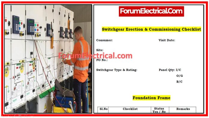
Before starting erection and commissioning, record consumer information, visit date, site data, purchase order (PO) number, switchgear type & rating, and panel amount (I/C, O/G, B/C).
This preparatory documentation guarantees that all necessary information is available for reference throughout the procedure.
Foundation Frame
The initial phase entails preparing and inspecting the foundation frame. Check that the bed plate is leveled to -40 mm. Inspect the floor frame for damage and make sure the cross-sections are equal.
Floor frame leveling should be done to a tolerance of +/- 1 mm. Confirm that the cutout placement for the power and control cable entries matches the drawing (DRG).
Ensure that the bed plate welding on the floor frame is complete, as well as the floor frame earthing following the primary earthing.
If the floor level is three millimeters below the foundation frame, extra flooring work is required.
Erection of Panel
When erecting a panel, inspect the enclosure for external damage. If any damage is discovered, call your insurance company immediately.
When the enclosure is opened, inspect the panel to ensure it is in good condition.
Check that the panels are securely fastened and level on the floor frame. If any gaps are discovered, they should be plugged properly.
Also, check that any extra holes in the panels are sealed and that all packaging materials are removed.
Panel Testing – Mechanical
Mechanical panel testing is needed for commissioning. Remove any packaging materials utilized to lock the breaker, as instructed on the panel board.
Verify that the breaker has been moved to the test and service positions, and that the test & service position switches and contacts are operational.
Open the front cover of the breaker & assess its condition; if necessary, double-check the tightness of all nuts. Manually charge the spring & test the breaker to guarantee good operation.
Check the auxiliary switch contacts in both positions and ensure the limit switches are operational. Inspect the contacts on both the pole and the panel sides to ensure they are in good shape.
Examine the movement of the shutter, the condition of the busbar-support insulator, & ensure that the bus bars are manufactured according to the drawing.
Examine and ensure the breaker’s contact alignment with the panel, as well as the bus bar bolt tightness.
Panel Testing – Electrical
Electrical panel testing ensures proper operation.
Check the inter-panel wiring for continuity and measure the control voltage. Before energizing the control voltage, make sure all of the panel’s MCBs are off. After connecting the control voltage, check it across all panels and then turn on the MCBs in each panel one by one. Inspect the breaker’s operation and confirm the travel through the relay.
Test all types of relays (current and voltage) to guarantee appropriate operation, following the instructions and noting the results separately. Complete the primary injection test on the current transformer (CT), follow the instructions, and record the results individually.
Check the contact resistance at the breaker and bus joints, referring to the instruction page and recording the results consecutively. Perform a ratio check on the potential transformer (PT) and note the results, then check the open delta voltage.
Check the meters with the secondary injection test, and then perform the Megger and high-voltage (HV) tests as indicated, documenting the results separately.
Conclusion
After completing the checklist’s essential checks, the switchboard can be commissioned to ensure its operational readiness. Document any general comments on the process, and ensure that the site supervisor, site engineer, and commissioning engineer all provide their approval, certifying the successful completion of the switchgear erection and commissioning process.


