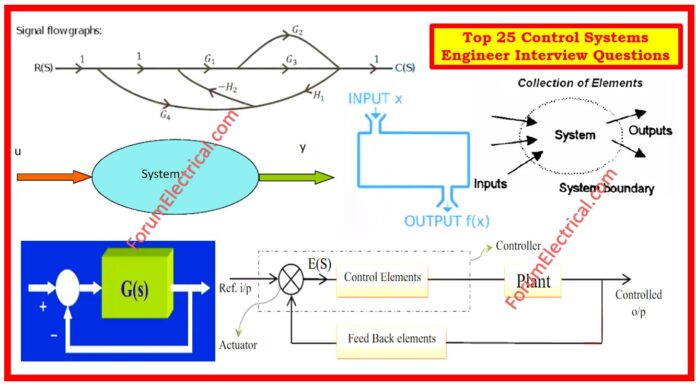
1). What is meant by System?
When the number of connected parts performs a given purpose, the group of elements is referred to as a system, or the interconnection of different components for a particular function.
2). What are Control Systems?
Control systems are intended to control, command, direct, or govern the actions of other devices (or) systems.
These systems are essential in ensuring that desired outputs are obtained by constantly monitoring and modifying the inputs & processes involved in a system.

3). What are the different components of a control system?
Control systems are typically composed of four major components:
- Input: This is the signal (or) data that enters the system.
- Controller: The controller processes the input data & determines which actions to execute.
- Plant: The plant is a system that controller oversees or regulates.
- Output: The output is the result of the system’s operations in response to the controller’s commands.
4). What is the function of a control system?
The basic function of a control system is to keep the system’s output at a target level (or) within a specific range.
Control systems provide the stability, efficiency, accuracy, & performance optimization of many processes and technologies.
5). What are the different types of control systems?
There are 2 different types of control systems.
- Open-Loop Control System.
- Closed-Loop Control System.
6). What is Open-Loop Control System?

An open-loop system is one in which the output is not transmitted back to input for the purpose of regulating or correcting errors. Disturbances from the outside environment or changes in surrounding environment are not taken into effect.
Ex: Electric Heaters, Toasters, and Washing Machines
7). What is Closed-Loop Control System?
The feedback from the output is used by closed-loop systems, also known as feedback, to make the necessary modifications in order to maintain the desired level of performance.
The accuracy and stability of these systems are superior to those of open-loop systems.
Ex: The cruise control system in automobiles and the temperature control system in constructions.

8). What is a Control Loop?
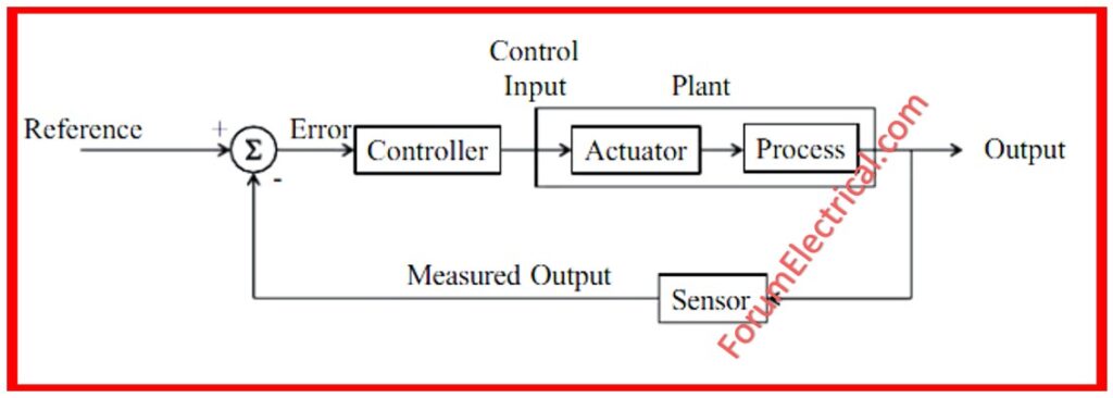
A control loop is the way that information flow in a control system. It normally comprises of four major elements:
- Set Point: The intended value (or) level that system seeks to achieve.
- Sensor: Sensor measures the actual output (or) process variable.
- Controller: Analyzes the sensor’s measurement to the set point & chooses corrective actions.
- Actuator: The actuator receives signals from controller & makes modifications to the process.
9). What is the definition and significance of transfer function in control systems?
The transfer function in the frequency domain depicts the relationship among a system’s input & output.
It facilitates understanding of the way a system responds to multiple inputs at different frequencies.
Transfer functions are important because they may reduce complicated systems to mathematical representations that can be analyzed and controlled successfully.
10). What is the difference between stability and accuracy in control systems?
Stability refers to a control system’s capacity to return to the equilibrium following shocks.
A stable system guarantees that output remains consistent across time, preventing oscillations (or) deviations from expected values.
On the other end, accuracy refers to how closely a system’s output corresponds to the desired set point or reference value.
An accurate control system reduces errors between the actual and expected outputs, resulting in exact performance.
11). What is Feedback Control Systems?
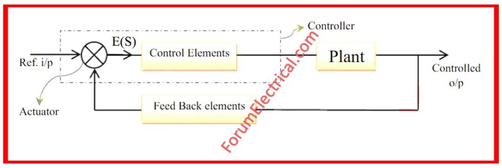
A feedback control system regulates its output to attain an ideal value by continuously assessing its performance and modifying inputs.
It functions on the feedback principle, in which the output is monitored and compared to a reference or intended value (setpoint).

When there is a deviation (or) error, the system performs corrective measures to reduce the error & bring the output closer to the desired value.
12). What is Feedforward Control Systems?
Feedforward control is a proactive method in control systems that anticipates and mitigates disturbances before they adversely affect the system.
Unlike feedback control, which responds to errors after they occur, feedforward control projects the effects of disturbances using a system model and takes corrective action ahead of time.
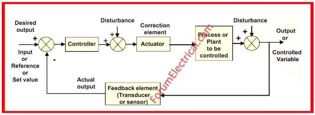
13). What are the Components of a Feedback Control System?
The components of the feedback control systems are:
- Sensor: Detects output (or) process variables.
- Comparator: Compares real outputs to reference values.
- Controller: Controller determines corrective measures based on comparison results.
- Actuator: Returns control signals generated by controller into the system.
14). What are the advantages & disadvantages of the closed-loop control systems?
Advantages of the Closed-Loop Control Systems
- Improved accuracy & precision in achieving desired results.
- Increased stability against external disruptions.
- Enhanced efficiency using continuous feedback mechanisms.
Disadvantages of the Closed-Loop Control Systems
- In contrast to open-loop systems, the design and implementation are more complex.
- Increased initial expenses due to the additional components like sensors & controllers.
- If not correctly tuned or configured, the system may become unstable.
15). What is the feedback mechanism in control system?
In a control system, feedback occurs when the input is provided to the system, the output is sampled, & the proportional signal is subsequently fed back to input for the automatic error correction for additional processing to get the desired output.
16). What is Gain Margin?
Gain margin is the level of gain that varies before the system becomes stable. If we constantly increase the gain up to a specific threshold, the system will eventually become marginally stable, but if the gain varies further, the system will become unstable.
From a mathematical perspective it is the reciprocal of magnitude of G(jω)H(jω) at phase cross-over frequency.
17). What is Signal Flow Graph?
SFG (Signal Flow Graph) is a graphical representation of the connection between the variables in a set of linear equations.

Signal flow graphs require no reduction technique or procedure.
18). What are the essential characteristics of Signal Flow Graphs?
The key features of signal flow graph are:
- It displays a network with nodes representing system variables and direct branches connecting them.
- A set of equations is shown in an SFG diagram. It consists of nodes and branches, and each branch of SFG has an arrow that shows the signal’s flow.
- It only applies to linear system.
19). What is an Order of a System?
The order of a system is the maximum derivative of the order of an equation that the system possesses by default.
Similarly, the transfer function’s denominator contains the highest power of ‘s’.
20). What is the Resonant Peak?
The term “Resonant Peak” refers to the possibility of the closed-loop transfer function reaching its greatest possible value.
A considerable overrun in the transient response is indicated by a high resonant peak value.
21). What is a Servomechanism?
When a servomotor is paired with a rotary encoder (or) a potentiometer to create a servomechanism. In this system, a potentiometer generates an analog signal that indicates the location, while an encoder offers position & speed feedback.
22). What is the Phase Crossover Frequency?
When the phase of an open loop transfer function approaches 180 degrees at a specific frequency, this is referred to as the phase crossover frequency.
23). What is the Phase Margin?
Phase Margin is the term used to describe the additional phase lag which is required at the frequency of the gain crossover. This occurs when the system is on a point of instability.
24). What Is Pole of the System?
The value for which the function F(s) turns infinite is known as the F(s) Pole, where F(s) is a complex variable function.
25). Where is Servomechanism used?
A servomechanism is used in control systems to vary the mechanical position of the device using output.
The Servomechanism is commonly employed in a Governor value position control mechanism that is utilized in power plants to take the speed of the turbine and process it using the transducer, with the final value being a mechanical movement of the value.
However, currently governor value position control is accomplished by electronic controls that employ power thyristors.
This method is also utilized in the robotic hand movement.


