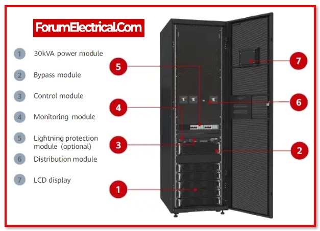
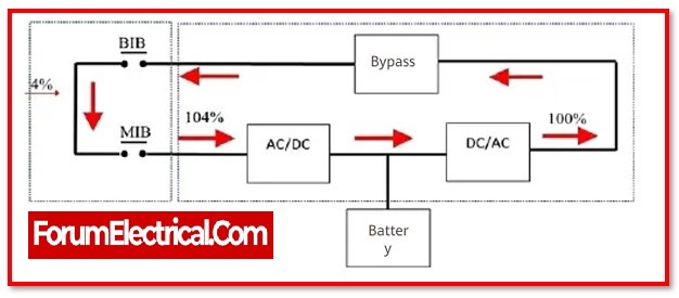
An electrical device known as an uninterruptible power supply, often known as a UPS or uninterruptible power source, delivers emergency power to a load whenever the input power source (or) mains power fails. A UPS varies from an auxiliary, emergency, or standby power system (or) standby generator in that it will supply energy from batteries to give almost immediate protection from input power interruptions.
Most uninterruptible power supplies have an on-battery runtime that is only a few minutes long, but it is enough to start a standby power source (or) appropriately shut down protected equipment.
It is still possible and unpredictable for errors to develop in users’ installations (or) in the public distribution system. Uninterruptible power supplies (UPS) are frequently used in information technology installations because of how sensitive they are to power supply variations and distortions.
Some setups also come with a backup generator that may be programmed to start three minutes after a power outage is detected and a second UPS that is fed by a different feeder. Certain facilities will physically switch over to backup generation in advance if the danger from the environment or other local events is significant enough. Perform the following tests during installation and subsequently on a regular basis (depending on contractual agreements) once the system is commissioned to ensure that the contingency supply systems work as intended.
The testing that takes place during the installation phase has been divided up into two stages:
1). Pre-installation – test – Perform a test before connecting any significant loads during the pre-installation phase.
2). Combined Test – Connect up the essential loads and run the test while cycling the standby generator ON and OFF.
Pre-Installation Test
1). UPS functional and alarms tests
Purpose: Check the functionality of the UPS, as well as the LED display and the alert messages.
2). UPS specification test
Purpose: Check and record readings of the UPS’s parameters (need two power loggers).
Procedure: Record the voltage, current, actual power, apparent power, power factor, and total harmonic distortion (THD) of the voltage and current at both the input and output of the device. To get a balanced load, vary the load from 0% to 100% in 25% intervals.
For testing under an unbalanced load, use the following load matrix:
| Sequence | Phase-1 | Phase-2 | Phase-3 |
| 1 | 100% | 100% | 0% |
| 2 | 0% | 0% | 100% |
| 3 | 100% | 50% | 100% |
| 4 | 50% | 100% | 50% |
3). UPS burn-in test
Purpose: Verify that the uninterruptible power supply (UPS) system can function at the rated load in conditions of ambient room temperature.
Procedure: The procedure involves loading the UPS to its rated load and operating it for anywhere between eight and twenty-four hours, depending on the needs of the requirements.
4). UPS step load & bypass loss transient tests
Purpose: The purpose of this test is to demonstrate how the UPS module reacts to a transient response.
Procedure: Determine the transient reaction of the UPS for the following:
a). Load steps going from 0% to 100% to 0%
b). Load steps going from 0% to 50% to 0%
c). Load steps going from 50 % to 100 % to 50 %
d). The UPS is operating with the loss of the bypass mains
5).UPS start & stop test
Purpose: The purpose of this test is to demonstrate that the UPS is operating correctly when it is turned ON& OFF with a full load.
Procedure: The procedure is turning the inverter ON & OFF while the module is operating at a load of both 50% and 100 % respectively. Record transients, as well as the load voltage and current, as well as the mains 2 and mains 1 currents.
6).UPS full load battery discharge test
Purpose: The purpose of this test is to demonstrate that the UPS can operate correctly for 15 minutes under full load while the power is out.
Procedure:Using a battery monitoring system, take readings of individual battery cells both before and after they have been discharged.
7). UPS loss & return of mains test
Purpose: The purpose of this test is to demonstrate proper operation both when the mains are lost and when they are restored.
Procedure: The procedure is to run the module with a normal load while turning on and off the UPS main input. Make sure to record any transients, as well as the load voltage and current, as well as the mains 1 current.
8).UPS loss & return of battery test
Purpose: The purpose of this test is to demonstrate proper functionality during the loss and subsequent return of the UPS batteries.
Procedure:The procedure involves running the module at a regular load while turning the primary battery breaker of the UPS on and off. Transients, load voltage, load current, and mains will all be recorded.
9).UPS load transfer test
Purpose:The purpose of this test is to demonstrate proper operation when moving loads.
Procedure:While the module is operating at its typical load, switch the UPS off and then back on again until the load is on the static bypass. From static bypass to UPS, this operation is carried out in reverse. Take note of the load voltage as well as the load current and the bypass current.
10).UPS transfer to bypass & back test
Purpose: The purpose of this test is to demonstrate proper operation with an external bypass.
Procedure: The procedure involves moving the load from the internal bypass to the external bypass and then back to the UPS. Take measurements of the load’s voltage and current.
Combined Test
Repeat the same tests with the critical loads and the backup generator connected, but this time with the load reduced to 0% and increased to 100%. Maintaining appropriate levels of waveform distortion and transients requires careful monitoring of the transfer between the primary power source, the uninterruptible power supply (UPS), and the backup generator.
Maintenance Test
Maintaining an emergency supply system should involve doing maintenance checks on a regular basis (at least once per month). Use the combined testing technique for every component, with the exception of the standby generator, which only needs to be evaluated once year.


