UPS System Start-Up and Commissioning
- Starting up and commissioning a UPS (Uninterruptible Power Supply) system is a critical process to ensure it functions as intended.
- The following guidelines are provided, which should be adapted as per the specific instructions from the UPS manufacturer and in accordance with organization’s requirements:
- Verifying Proper Electrical Connections
- Verifying Initial System Set-Up
- Simulation of Line Power Source Loss
What is UPS Commissioning?
Verifying Proper Electrical Connections
Verifying proper electrical connections during the start-up and commissioning of a UPS system is crucial for ensuring the safety of personnel and the reliable operation of the equipment. Here are the key purposes and steps for verifying these connections:
Purposes for Verifying Proper Electrical Connections:
- Confirming that no loose connections exist is vital to prevent arcing, electrical faults, and potential hazards to personnel. Loose connections can lead to sparks, fires, and equipment damage.
- Verifying correct interconnecting wiring is essential to protect the system equipment from damage. Incorrect wiring can lead to short circuits, overloads, and operational issues.
Steps for Verifying Proper Electrical Connections:
- Ensure that all electrical components are installed as per the design documents and manufacturer’s specifications.
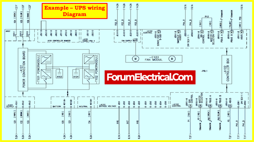
- Verify that all field wiring has been installed according to the project’s electrical drawings and wiring diagrams.
- Inspect all electrical terminations, field connections, and vendor-supplied equipment for tightness.
- Loose connections can be a source of high resistance, which may lead to overheating and potential electrical hazards.
- Examine the insulation on electrical conductors for any signs of breaks, voids, or materials stress. Damaged insulation can lead to electrical faults and shorts.
- Check that electrical conductors are free of any sharp edges or moving parts that could damage the insulation. Sharp edges or moving parts can cause abrasion, leading to insulation failure.
How do I setup an uninterruptible power supply?
Verifying Initial System Set-Up
The verification of the initial system set-up for a UPS system involves checking its operational functions and configurations. This process covers the following aspects:
- Initial Conditions
- System Setpoints
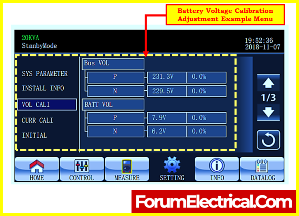
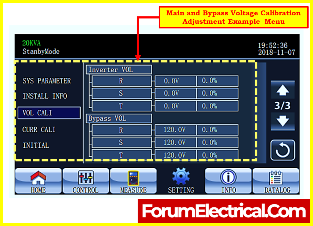
- Calibration Checks
- Switching Functions
Verifying Initial Conditions
During the initial setup of the UPS system, several critical conditions need to be confirmed. The Electrical Engineer’s responsibilities include the following:
Verification of Technical Manuals
- Ensure that all technical manuals provided by the UPS system manufacturer have been received.
- Confirm that these manuals are relevant to the specific installation. It is essential that the manuals match the installed equipment precisely, as equipment-specific manuals are often used.
- Mismatched or non-applicable manuals can lead to significant issues and complications during installation and operation.
Overcurrent Protection Fuses
- Verify the installation of overcurrent protection fuses and ensure they are of the correct rating.
- Undersized fuses may trip unnecessarily, disrupting the system’s operation.
- Oversized fuses can allow excessive current flow, potentially damaging the equipment.
- Properly sized fuses are crucial for system safety and performance.
Incoming Power Sources Check
- Check the availability and integrity of incoming power sources, which typically include:
- A preferred AC power source that connects to the inverter circuit.
- An alternate AC power source that links to the static switch and manual bypass switch.
- In some installations, a third incoming AC power source may be used, connecting to the manual bypass switch, while the alternate source supplies only the static switch.
- Ensure that these power sources are correctly configured, as they are essential for the UPS system’s redundancy and reliability.
Inverter and Battery Charger Enclosure Ventilation Fans
- Verify the proper operation of ventilation fans within the inverter and battery charger enclosures.
- Malfunctioning or obstructed fans can lead to excessive temperatures within the enclosures, which, in turn, may result in operational failures and the premature failure of electrical components.
- Maintaining the correct operating temperature is critical to ensure the reliable and efficient performance of the UPS system.
System Setpoints
Alarm Setpoints
Purpose of Verifying Alarm Setpoints:
- Verify alarm setpoints during UPS system start-up to monitor critical parameters and prevent system failure due to extreme conditions.
Alarm Points Monitoring:
- Alarm points monitor specific parameters and trigger alarms when these parameters reach or exceed specified limits.
- Operating near these limits risks component or system failure.
Alarm Types:
- DC Input Voltage High Alarm: Activates when the dc input to the inverter exceeds a specified maximum operating condition. The setpoint should be around +5.0% of the nominal dc input voltage.
- DC Input Voltage Low Alarm: Activates when the dc input to the inverter falls below a specified minimum operating condition. The setpoint should be approximately -5.0% of the nominal dc input voltage.
- Alternate Voltage/Sync Source Not Available Alarm: Alerts when the alternate power source voltage deviates from nominal voltage by +/- 10% or when frequency deviates by +/- 5%.
- Static Switch Position Indication Alarm: Energizes when the static switch transfers from the inverter to the alternate power source, indirectly indicating inverter failure.
- Output Failure Alarm: Warns of a loss of inverter output power if voltage deviates beyond +/- 10% or frequency deviates more than +/- 5.0% from the nominal 60 Hz value.
- Enclosure Over Temperature Alarm: Alerts of elevated inverter equipment temperatures, which can lead to abnormal output conditions and potential equipment failure.
Control Setpoints:
Purpose of Verifying Control Setpoints:
- Check control setpoints to establish UPS system operating conditions, ensure functionality, and establish baseline conditions.
Setpoint Adjustments:
- Output Voltage: Maintain voltage within +/- 10% of nominal voltage (adjustable on the inverter’s internal control module).
- Output Frequency: Ensure the output frequency is 60 Hz +/- 5.0% (adjustable on the static inverter’s oscillator board).
- Phase Relationship: Check and adjust the phase relationship between inverter output and the ac line.
- Waveform Purity and Harmonic Distortion Level: Monitor the waveform with a spectrum analyzer for harmonic distortion below 4%.
- Static Switch Transfer/Re-Transfer Voltage Monitor: Monitors inverter output voltage for deviations and manages transfers to the alternate source.
- Static Switch Transfer/Re-Transfer Frequency Monitor: Monitors inverter output frequency and controls source transfers.
- Battery Isolation Circuit Breaker Shunt Trip: Protects the battery from over-discharging by tripping the circuit breaker in case of low dc voltage.
Voltage Adjustment Procedure:
- Adjust output voltage when no load is applied to the static inverter by varying the delay time or firing angle of the SCRs.
- Verify output voltage under load and monitor for voltage level transients and waveform purity.
- Firing angle adjustments affect voltage magnitude, not frequency or phase angle.
Frequency Adjustment:
- Check and adjust output frequency to ensure it is 60 Hz +/- 5.0%.
- Monitor frequency with the ac source reference deenergized to prevent external synchronization.
- Use an oscilloscope to confirm a 16.7-millisecond period for one cycle.
Phase Relationship Adjustment:
- Check phase relationship between the inverter output and the ac line using a dual trace oscilloscope.
- Ensure the phase relationship is zero.
Static Switch Control:
- Monitor inverter output voltage for deviations to control the static switch, which transfers to the alternate source when voltage fluctuates beyond +/- 10%.
- Re-transfer to the inverter source occurs when voltage returns within +/- 2.0% of nominal voltage for at least 30 seconds.
Calibration Checks
- As part of UPS system setup and commissioning, calibration checks are essential.
- Panel Meters are used to monitor crucial system parameters continuously.
- The accuracy of panel meters is verified by comparing their readings to those obtained from calibrated test instruments.
- The readings on panelmeters should ideally fall within a tolerance of +/- 2.0% compared to the calibrated test instrument values.
- Ensuring accurate panel meter readings is vital for the reliable operation and maintenance of the UPS system.
Switching Functions
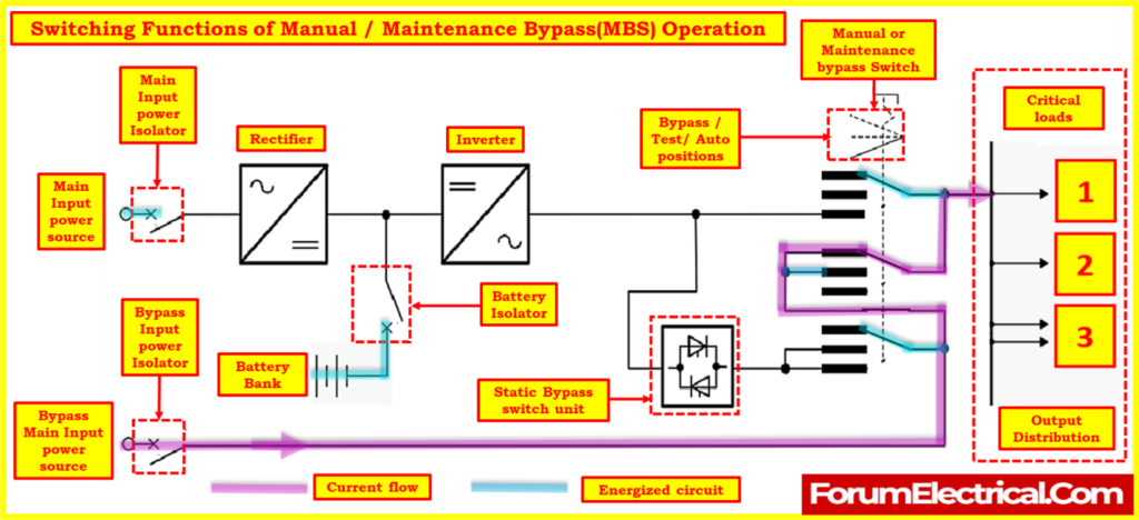
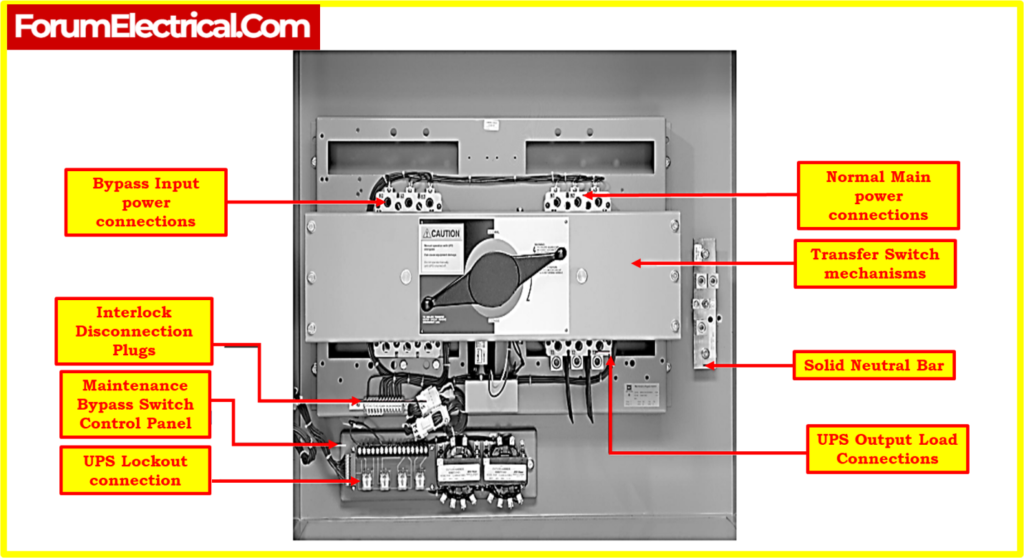
Manual/Maintenance Bypass Switch
- Used in UPS systems for maintenance and testing.
- Connects critical AC loads directly to a reliable power source without load downtime.
- Isolates the inverter for safe inspection, testing, and maintenance. Two-way bypass switches serve multiple functions:
- Shunts power around the inverter without interrupting its output power, ensuring uninterrupted power to critical loads in case of inverter failure.
- Allows electrical testing and adjustment of the inverter without affecting power to the critical load.
- Electrically isolates the inverter from the preferred and alternate power sources and the critical load for inspections and maintenance.
Panel meter Selector Switches (3-Phase Systems)
- Used in three-phase UPS systems to monitor individual parameters with one meter.
- Ideal for systems that do not require simultaneous continuous monitoring of all parameters, offering cost-effectiveness.
- Selector switches enable monitoring of the following parameters:
- Voltage with switch positions: A-B, B-C, A-C, L-N.
- Frequency with switch positions: A_, B_, C_, L-N.
- Amperage with switch positions: A_, B_, C_.
Simulation of Line Power Source Loss
Purpose
- Verify proper UPS system operation for an uninterrupted, bump less transfer to the alternate power source in the event of a line power source loss.
Key Observations
- Two conditions are essential for UPS system testing:
- Transfer of power from the preferred power source to the alternate power source.
- Transfer of power from the alternate source back to the preferred source.
Sequence of Events for Simulated Line Power Source Loss Test
- In automatic mode, the inverter provides power to the critical load when the preferred power source is available. A transfer and transfer signal will occur if:
- Inverter output voltage or frequency exceeds normal ranges (+/- 10% voltage, +/- 5% frequency).
- An external transfer signal, such as the inverter in current limit mode, is detected.
- Line power source loss can be simulated by:
- Opening the DC input breaker to the inverter.
- Opening the AC input breaker to the inverter and the battery output breaker.
- Opening the battery output breaker and varying AC voltage outside the normal range using a variable AC input source.
- Transfer to the alternate source will occur if no transfer inhibit signal is present.
- Conditions resulting in a transfer inhibit signal and a blocked transfer include:
- Alternate power source voltage or frequency outside normal ranges (+/- 10% voltage, 60 Hz +/- 5% frequency).
- Presence of an external transfer inhibit signal like a sync disconnect signal.
- The AC alternate source powers the critical loads until:
- The external transfer signal is removed from the preferred source sensing circuit.
- Inverter output voltage remains within +/- 2% of the nominal voltage for at least 30 seconds.
- Inverter output frequency stays within +/- 2% of the nominal frequency for at least 30 seconds.
- When these conditions are met, the critical load is transferred back to the inverter output, which is the preferred power source.


