
- What is Series Circuits?
- What is Voltage in Series Circuits?
- How to calculate voltage in a series circuit?
- What happens to the voltage when multiple circuits are connected together in series?
- Voltage Drop in Series Circuit
- To what significance does voltage drop in a series circuit remain constant?
- Voltage Division Formula for Series Circuits
- Application of the Voltage in Series Circuits
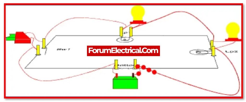
What is Series Circuits?
When two (or) more electrical components are connected to one another in a chain-like arrangement within a circuit, this configuration is known as a series circuit or series connection.
What is Voltage in Series Circuits?
Charge can only travel through a circuit of this type in one direction because there is only one path for it to take.
Voltage refers to the potential difference in charge that can exist between two points within an electrical circuit.
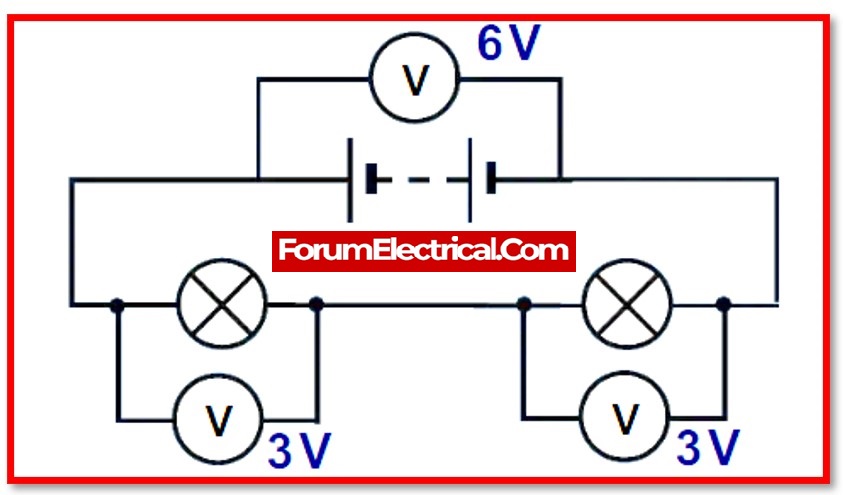
Voltage in series circuit is the components in a circuit that is connected in series divided equally the voltage that is supplied by the battery.The voltage of the battery is therefore equal to the sum of the potential differences that exist between the components.
In order to calculate the voltage that is series in a circuit that has its components linked in series, it’s necessary to first determine the total voltage that is given by the source and then multiply that value by the total number of components that are present in the circuit.
This shows that the voltage in a series circuit is kept at the same level at each and every point along the circuit. This is the condition because the voltage cannot fluctuate.
In series circuits, the source voltage divides in direct proportion to the value of the resistors.
Specifically,
V T = V R1 + V R2 + V R3
Example:
A circuit’s battery is its source of electrical energy, which enables a charge to move through the battery while simultaneously producing a potential difference between the two ends of an external circuit.
If assume that a cell has a voltage of 2 volts, then the potential difference that it generates all across external circuit will also be 2 volts.
How to calculate voltage in a series circuit?
Applying Ohm’s law, which states that
V = R X I
allows one to determine the circuit voltage for each individual element in a series circuit.
In addition, if the resistance of the element is unknown, from Kirchhoff’s Voltage law, the Kirchhoff loop rule can be used to help calculate the voltage that is present across the element in the circuit.
Remember that the Kirchhoff loop rule can be written as:
VT=V1+V2+V3
Where,
VT is the total voltage of the power supply.
This rule applies when there are three electric elements connected in series with a power source.
What happens to the voltage when multiple circuits are connected together in series?
The voltage is reduced because the overall resistance of the circuit is greater than the sum of the individual resistances of the electric components that form the series circuit. Remember that the current, in contrast to the voltage, does not change at any point throughout the series circuit.
Voltage Drop in Series Circuit
When compared to the value of the electric potential at the negative terminal, the value at positive terminal is higher by 2 volts.
Therefore, a loss of two volts in the electrical potential is caused whenever charge is transferred from the positive terminal to the negative terminal.
This phenomenon is referred to as a voltage drop.
This occurs when the charge’s electrical energy is converted into some other forms (mechanical, heat, light, etc.) while it is travelling through components (resistors or load) in the circuit.
This can take place in a number of different ways.
The sum of all of the individual voltage drops that occur within the series circuit is equal to the total voltage that is present in the circuit.
A potential difference is created across each individual resistor in a series circuit as a result of the flow of current through each component of the circuit in that order.
This phenomenon is referred to as voltage drop, and the magnitude of the voltage drop is directly proportional to the resistance value.
If the resistance value is increased, then the voltage drop across the resistor will also be increased.
ET = E1 + E2 + E3…
It is possible to formulate it in mathematical terms as:
ΔVBattery = ΔV1 + ΔV2 + ΔV3
Using Ohm’s law, can calculate the voltage drop of an individual component as follows:
ΔV1 = I x R1
ΔV2 = I x R2
ΔV3 = I x R3
To what significance does voltage drop in a series circuit remain constant?
The resistance of an individual component in a series circuit determines the voltage drop across that circuit, hence the outcome is nil. The voltage drop is determined by the formula V=R x I.
Voltage Division Formula for Series Circuits
If have the applied voltage (V) and the total resistance (RS) in a loop, can determine the “voltage divider rule,” which states that VRi is equal to Ri/RS multiplied by V, to get the voltage drop (VRi) across each resistor Ri.
VRi = (Ri/RS) x V
Application of the Voltage in Series Circuits
- Battery for the fire alarm.
- batteries for the remote control, toys, and so forth.
- Applications involving lighting, such as in a railway or a Christmas tree, etc.
- Voltage divider.
