
- What is Armature?
- Components of an Armature
- What is the function of an Armature?
- What rotates an electric motor armature?
- What is the armature of a DC motor?
- What is armature in coil?
- How to Test (check) an Armature?
- How does an Armature of a Motor (Motor Armature) function?
- How the Armature of a Generator Works?
- Applications of an Armature
What is Armature?
An armature is a power-generating component of an electric machine that may be a spinning or stationary section of the machine.
The armature may interact with the magnetic flux in the gap of air, and the field element can contain any stable magnets or electromagnets fashioned with a conducting coil like another armature, which is known as the doubly-fed electric machine.
The armature always functions as a conductor, sloping normal to both the field and the motion direction, torque or force.
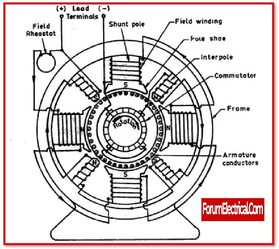
Components of an Armature
An armature may be made up of many components, including
- The Core,
- The Winding,
- The Commutator, and
- The Shaft.
A magnetic field is produced by excitation of the field coil.
The shaft’s mechanical power is transformed into electrical power by the armature EMF driving the armature current.
1).The Core
The armature core might be made up of several thin metal plates known as laminations.
The thickness of the laminations is about 0.5mm and is determined by the frequency at which the armature is meant to operate. With a push, the metal plates are stamped out.
They are round in shape due to a hole hammered out of the core when the shaft is pressed, along with the slots stamped in the area of the edge where the coils would eventually rest.
The core is made up of metal plates that are connected together. To generate the sum of lost energy during heat in the core, the core might be made with stacked metal plates rather of a steel piece.
The loss of energy is referred to as iron losses, which are caused by eddy currents.
These are minute magnetic fields that arise in the metal as a result of the rotating magnetic fields that may be detected anytime the unit is turned on.
If the metal plates employ eddy currents, they may develop in a single plane while also considerably reducing losses.
2).The Winding (Armature Winding)
Before winding proceeds, the core slots will be shielded against the copper wire inside the slots coming into contact with the laminated core.
Coils are inserted into the armature slots and connected to the commutator while spinning.
This may be accomplished in a variety of ways depending on the armature design.
Armatures are divided into two types:
- Lap wound armatures and
- Wave wound armatures
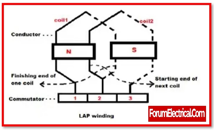
Lap Wound Armature
In a lap wound, the terminal end of one coil is coupled to a commutator section as well as the main end of an adjacent coil.
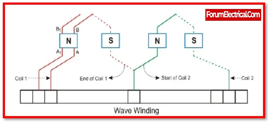
Wave Wound Armature
In a wave wound, the coil’s two ends will be coupled with commutator segments separated by some distance between the poles.
This enables the sequential addition of voltages inside the windings between brushes. This kind of winding requires just a few of brushes. The number of lanes in the first armature equals the number of poles and brushes.
In certain armature designs, two or more distinct coils will be placed in a comparable slot and connected to adjoining commutator segments. This is possible if the needed voltage across the coil is thought to be high.
The strength of the field in the slot will be large due to the distribution of the voltage across three independent segments, but it will minimise arcing over the commutator and make the device more competent.
The slots in some armatures are also twisted, which is possible since each lamination is slightly out of alignment.
This may be done to reduce cogging and create a level rotation from one pole to another.
3).The Commutator
The commutator is pushed onto the shaft and kept in place by a coarse knurl comparable to the core.
The commutator may be designed using copper bars and separated by an insulating substance.
This material is often a thermoset plastic, however in previous armatures, sheet mica was utilised.
When positioned on top of the shaft, the commutator must be exactly associated with the core slots because the wires from each coil will emerge from the slots and connect with the commutator bars.
To ensure that the magnetic circuit operates properly, the armature coil must have a correct angular displacement from commutator bar to which it is connected.
4).The Shaft
The machine’s shaft is utilised to transfer mechanical energy. It is a strong rod supported by two bearings.
To reduce harmonic distortions, the length, speed, & bearing points are chosen.
The shaft thickness is selected to convey the torque needed by the machine. It also has to be firm enough to manage any out-of-balance forces.

What is the function of an Armature?
The communication of the two magnetic fields may cause the armature to rotate.
The field winding may create one magnetic field, while the armature can generate another when voltage is given to the brushes to make contact with the commutator.
As current flows through the windings of an armature, it generates a magnetic field. This is caused by the field formed by the field coil.
This will result in the strength of attraction towards one pole and aversion against the other.
When the commutator is attached to the shaft, it moves to a same degree and activates the pole.
The armature will continue to spin as it chases the pole.
If the brushes are not powered, the field will be agitated and the armature will be driven mechanically.
The applied voltage is alternating current (AC) because it approaches & flows away from the pole.
Moreover, since the commutator is connected to the shaft and often activates the polarity as it circles, the genuine output may be seen across the brushes in DC.
- Electric motors or
- Generators
are made from armatures.
To communicate between the two magnetic fluxes, the armature is used.
1). Function of Armature in Electric Motor
An EMF is created when an armature is utilised as an electric motor because of the relative motion between the fluxes produced by the field winding & the armature winding.
This EMF will work against a rotor’s torque and an armature’s current. Hence, mechanical power is created by converting electrical power via the use of a shaft, the toque generated by the rotor is transmitted to spin other objects.
2). Function of Armature in Electric Generator
In most conditions, the armature is employed as a rotor when it is used as an electric generator.
And a diesel engine (or) prime mover was used to mechanically move the armature.
What rotates an electric motor armature?
Electric motors turn electricity into mechanical energy. .
Fleming’s left-hand rule determines the force on a current-carrying conductor in a magnetic field.
The motor creates a revolving magnetic field when the stator is supplied. This magnetic field turns the armature (rotor).This is sometimes called a synchronous motor’s armature reaction.
What is the armature of a DC motor?
A DC motor’s armature is a cylinder of magnetic laminations that are individually insulated. The armature is perpendicular to the cylinder’s axis. The armature is a rotating component that spins around its axis & is separated from field coil by an air gap.
What is armature in coil?
A DC motor consists of wire coils arranged in slots on the cylinder of ferromagnetic material known as the armature. The armature is supported by bearings & is free to rotate. It is positioned in the magnetic field generated by permanent magnets (or) electricity running via wire coils known as field coils.
How to Test (check) an Armature?
If there is damage to the armature, the motor won’t work.As a result, it is necessary to put an armature to the test. Remove the armature from the motor to test it.
1). Armature Test 1
The winding on the armature is first priority. To determine if the armature winding is open or shorted, users may do this test.
The ohmmeter will be used to check the resistance between the 180-degree-spaced commutator bars of each coil.
The ohmmeter’s reading will change based on the size of the motor. But, in this case, a precise reading is not important.
Check the resistance between each pair of commutator bars once you’ve gotten a baseline measurement by rotating the armature.
If each pair gives the same reading, the armature winding is satisfactory. The armature winding is shorted if the reading is dropping towards zero.
Furthermore, if the number on the display keeps going up, it means the armature winding is open.
2). Armature Test 2
It’s important to identify the faulty winding. This necessitates checking the resistance of the each bar.
If all the readings on each bar are the same, as in test 1, then the winding is OK.
Furthermore, if observe a sudden shift in resistance, it indicates the winding has been compromised.
3). Armature Test 3
In this test, users will use the armature stack to determine the resistance of each commutator bar individually.
For this evaluation, it is essential that the commutator bars not allow current to flow through them and into the armature stack.
How does an Armature of a Motor (Motor Armature) function?
An electric motor operates by changing electrical energy into mechanical energy through utilization of electromagnetic induction. If electric current is passed through a conductor placed in a magnetic field then it will deflect according to Fleming’s left hand rule.
The operation of an electric motor is based on the stator that produces a revolving magnetic field by permanent magnets or electromagnets. The armature may be the rotor with armature windings connected to the commutator and brushes as depicted below; The commutator changes the direction of the current in the armature windings as the latter rotates ensuring it is always in phase with the magnetic field.
When electricity flows through the armature windings, it interact with the magnetic field produced by the field windings to generate a torque that rotates the armature. It consists of a shaft to which an armature is connected that transmits mechanical power to the other devices.
How the Armature of a Generator Works?
Generators apply the law of electromagnetic induction whereby mechanical energy is transformed into electrical energy. In the case of a conductor that is moved in a magnetic field a process takes place called electromotive force by the help of Faraday’s laws.
In a generator the armature is usually the rotor which is rotated by a prime mover like a diesel engine or a turbine. The armature consists of armature windings which are in connection with the commutator and brushes. The stator has permanent magnets or electromagnets which develop the magnetic field that remains unaltered during the process.
Due to relative motion between the magnetic field and armature winding, an electromotive force is induced in the armature winding causing current through an external circuit. The commutator reverses the direction of the current through the armature so as to generate what is called the alternating current (AC).
Applications of an Armature
- The armature is the component of an electric machine that is responsible for the generation of electricity.
- The armature may function either as a rotor or a stator in the machine.
- This is used for the purpose of monitoring the current in DC motor applications.