What is Armature?
An armature is a rotating or stationary power-generating component in an electric machine. The armature can interact with the magnetic flux in an air gap, and the field element can be any permanent magnets or electromagnets shaped like another armature in a doubly-fed electric machine. The armature slopes normal to both the field and the motion direction, torque or force.
- What is Armature?
- Components of Armature
- 1). Core
- 2). Windings
- 3). Commutator
- 4). Shaft
- Armature Function
- What is the operation of an armature?
- a). Operation in Electric Motor
- b). Operation in Electric Generator
- What Causes an Electric Motor’s Armature to Rotate?
- What types of changes occur inside an electric generator whenever the armature is rotated?
- Applications of Armature
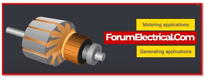
The armature carries AC on DC machines via the commutator or electronic commutation (ex: brushless DC motor).
Components of Armature
An armature can be constructed using a variety of components, including
- Core,
- Winding,
- Commutator, and
- Shaft.
These components form the armature.
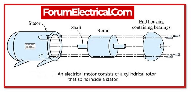
1). Core
The armature’s core is composed of laminated thin metal plates. Frequency affects lamination thickness. The thickness of laminations is 0.5mm thick. Laminated silicon steel reduces
- Eddy current loss and
- Hysteresis loss
in the armature core.
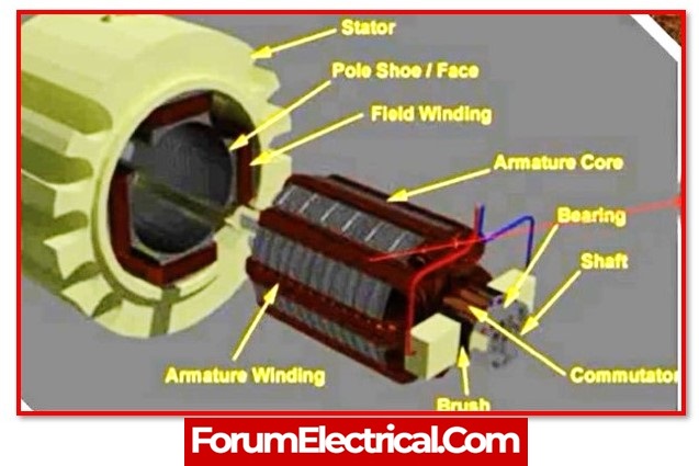
Armature cores are hollow cylinders. The shaft is inside the armature.
Number of slots are there inside the core. The armature winding is placed in armature core slots. The armature’s slots are heavily skewed to prevent magnetic locking and ensure smooth rotation.
2). Windings
Windings are inserted into armature core slots. Insulated armature winding prevents coil-to-core contact. Copper is used for winding. Some machines use aluminium to minimise costs. The armature can be lap- or wave-wound.
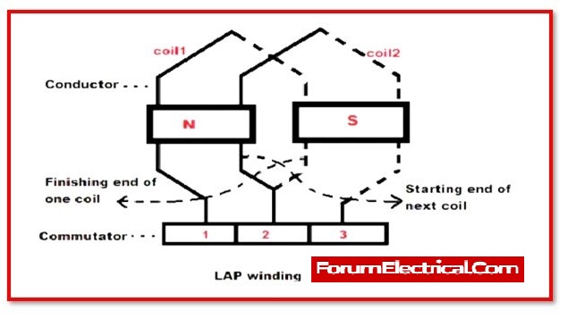
a). Lap Winding
In lap winding, current paths equate poles and brushes. In this winding, one coil’s completing end is attached to the commutator segment and the following coil’s starting end is connected to the same pole and commutator segment.
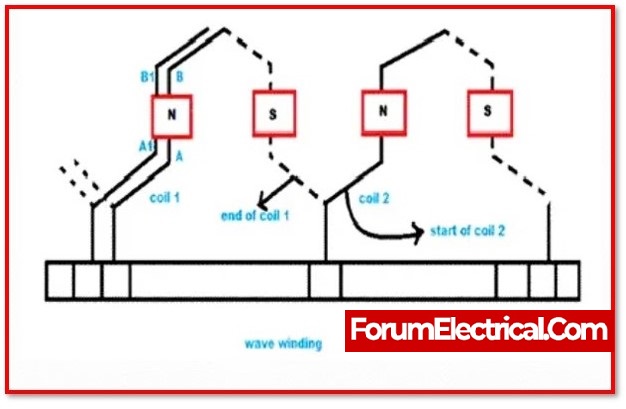
b). Wave Winding
Wave winding has two current paths. In this winding, both ends of each coil are connected to the commutator segment. This connects coils in series and provides voltages between brushes.
- Pole pitch and
- Coil span
explain these armature winding designs.
3). Commutator
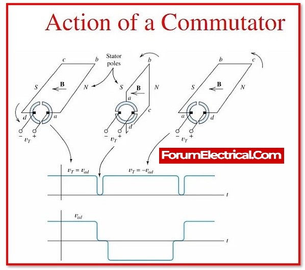
The commutator is constructed of copper bars that are separated from one another by insulating materials such as mica or plastic.
It is pressed against the shaft, and wires from each coil emerge from the slots to connect to the commutator bars. When the commutator is forced on the shaft, it must be exactly aligned with the slot.
To work efficiently for the magnetic circuit, the armature must be placed with correct angular displacement from the commutator bar.
4). Shaft
The shaft of an armature is a rigid (hard) rod attached between two bearings that regulate the axis of components mounted on it. It should be broad enough to send out the necessary torque with the engine and strong enough to regulate some of the out-of-balance forces.
- Length,
- Speed, and
- Bearing points
are chosen for harmonic distortion.
Armature Function
The interaction of two magnetic fields can cause the armature to rotate. The field winding can generate one magnetic field, while the armature can generate another while voltage is supplied to the brushes to make contact with the commutator. When current flows through the windings of an armature, it generates a magnetic field. This is caused by the field formed by the field coil.
This will result in the strength of attraction toward one pole and aversion (revulsion) toward the other. When the commutator is attached to the shaft, it moves to a same degree and activates the pole. The armature will continue to spin as it follows the pole.
If the brushes are not energized, the field will be excited and the armature will be driven mechanically. The applied voltage is alternating current (AC) because it approaches and flows away from the pole. However, because the commutator is connected to the shaft and often activates the polarity as it rotates, the actual output can be observed across the brushes in DC.
What is the operation of an armature?
Electric motors and generators both make use of a component called an armature. In order to communicate between the two magnetic fluxes, the armature is utilised.
a). Operation in Electric Motor
Because of the relative motion between the flux that is produced by the field winding and the flux that is produced by the armature winding, an induced electromagnetic field is created when the armature is employed in an electric motor.
This emf will act as a barrier between the current flowing through an armature and the torque that is generated by the rotor. Because of this, the electrical power is transformed into the mechanical power. With the help of a shaft, the torque that is generated in the rotor can be transferred to rotate other devices.
b). Operation in Electric Generator
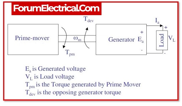
When the armature is used to power an electric generator, it typically assumes the function of the rotor in the generator. Additionally, the armature was mechanically operated with the assistance of a diesel engine, commonly known as a prime mover.
Excitation is applied to the field winding in order to produce a magnetic field. The armature electromagnetic field (EMF) is what drives the armature current, and as a result, the shaft’s mechanical power is turned into electrical power.
What Causes an Electric Motor’s Armature to Rotate?
Electrical energy is converted into mechanical energy by electric motors. In general, an armature is a rotating component of a machine.
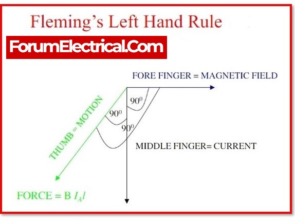
When a current-carrying conductor is placed in a magnetic field, it experiences force, and the direction of force is determined by Fleming’s left-hand rule.
When power is applied to the stator, a rotating magnetic field is created in the motor. The armature rotates due to the force exerted by the rotating magnetic field. This is sometimes referred to as a synchronous motor’s armature reaction.
What types of changes occur inside an electric generator whenever the armature is rotated?
A current is induced in the rotor windings as a result of continuous revolution through the rotating field. This induced current results in the generation of a field, which, in effect, cuts through the stator windings to result in the generation of power that is then delivered to the load.
Applications of Armature
- The armature is the component of an electric machine that is responsible for the generation of power.
- The armature can function either as a rotor or a stator in the machine.
- The armature is utilised for the purpose of monitoring the current in DC motor applications.


