 transformer connections including their working principles, advantages, disadvantages, applications & a simple illustration.)
 Transformer Connection? Complete Guide with Diagram")
What is an Open Delta Connection?
Definition
Open Delta connection also known as V-V connection is a method of attaining three phase (3 phase) power transformation using only 2 single phase transformers instead of the conventional 3 transformers required in a delta-delta (D-D) connection.
- What is an Open Delta Connection?
- Open Delta Configuration
- How Open Delta Connection works?
- Why open Delta?
- How Open Delta connection configured?
- Load Carrying Capacity – 57.7% Rule
- Capacity Calculation
- Transformer Overload Analysis
- Overload Factor Calculation
- Power Factor Considerations
- Advantages of Open Delta Connection
- Disadvantages of Open Delta Connection
- Comparative Analysis
- Applications of Open Delta Connection
- What is the difference between Open Delta and Closed Delta?
- Conclusion
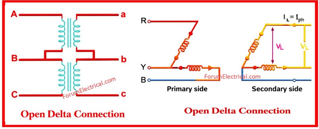
Open Delta Configuration
The open delta configuration represents an innovative and practical method to 3 phase power supply providing a cost-effective solution for specific applications.
This connection derives its alternative name V-V from the visual representation of two transformers connected in a V-shaped arrangement on secondary side.
Unlike other delta-delta transformer banks that require three transformers operating in parallel the open delta configuration achieves complete three phase power transformation using just 2 single phase transformers making it an economical alternative in certain conditions.

How Open Delta Connection works?
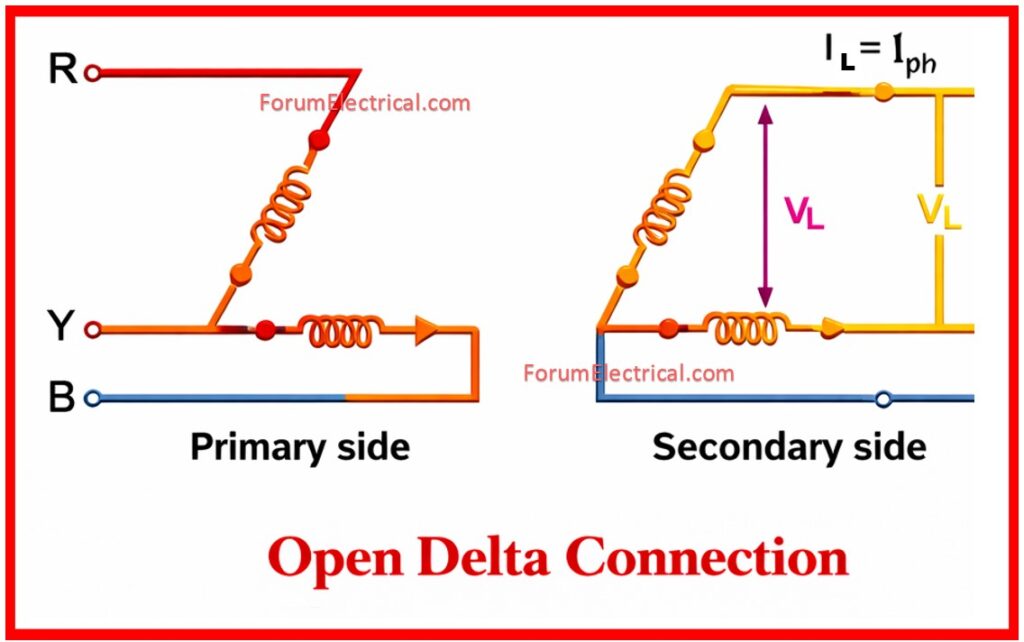
In an open delta connection 3 phase supply is connected to the primary sides of two single phase transformers.
The transformers are connected such that they form an incomplete (open) delta configuration.
The secondary sides of these transformers are arranged to provide a three phase output with voltages that are equal in magnitude but differ in phase by 120 degrees.
When no load is connected to the secondary side three equal voltages appear across the secondary terminals.
However the essential termination from a balanced delta-delta connection becomes evident when analyzing the power handling capacity and voltage characteristics under loaded conditions.
Why open Delta?
Open deltas only need the utility to install 2 transformers.
Future Capacity can be increased by simply installing a 3rd similar sized transformer vs installing 2 – 3 larger transformers.
How Open Delta connection configured?
2 single phase transformers are connected with their primary windings receiving three-phase supply (A, B, C phases).
The secondary windings are interconnected to produce three phase output.
One transformer carries phases A-B while the second transformer carries phases B-C creating the open delta arrangement.
The missing transformer (C-A phase) is what creates the “open” configuration.
Load Carrying Capacity – 57.7% Rule
One of the most significant characteristics of open delta connection is its reduced load carrying capacity compared to delta-delta connection.
This reduction is expressed mathematically and represents one of the key tradeoff when using this configuration.
Capacity Calculation
Delta-Delta Connection
SDD = √3 x VL x IL = √3 x VL x Iph
SDD = 3 x VL x Iph
Where
SDD – Delta-Delta Connection
VL – Line Voltage
IL – Line Current
Iph – Phase Voltage
Open Delta Connection
SOD = √3 x VL x IL = √3 x VL x Iph
Where
SOD – Open Delta Connection
Capacity Ratio
SOD / SDD = √3 x VL x Iph / (3 x VL x Iph)
SOD / SDD = √3 / 3 = 1/√3 = 0.577
Therefore open delta carries only 57.7% of the load that a delta-delta bank can carry over.
The basis for establishing the efficacy of open delta connections is this 57.7% capacity rating.
While this reduction may seem significant it is often acceptable for applications where the initial load is small and there is potential for future expansion.
Transformer Overload Analysis
When transitioning from a three transformer delta-delta bank to an open delta configuration (whether intentional / due to failure) the remaining 2 transformers experience increased stress. Understanding this overload is important for ensuring safe operation.
Overload Factor Calculation
Total Load / Individual Transformer VA Rating = √3 x VL x Iph / (VL x Iph)
Overload Factor = √3 = 1.73
Each transformer in an open delta configuration experiences approximately 1.73 times the current it would manage in a balanced three transformer delta-delta bank.
This 1.73 x overload is only suitable for short-term and temporary operation.
Continuous operation at this overload level will cause excessive heating and potential breakdown of the transformers.
Proper load management and cooling provisions are so essential.
Power Factor Considerations
The 2 transformers operate at separate power factors which distinguishes open delta connections.
This asymmetry creates imbalances in the system that should be understood and managed.
Transformer Power Factors
• Transformer 1
cos(30° – φ) with delivered power = kVA x cos(30° – φ)
• Transformer 2
cos(30° + φ) with delivered power = kVA x cos(30° + φ)
Where
φ – Load Power Factor Angle
The 30-degree phase shift between the two transformers operating points results from the geometry of open delta configuration.
Advantages of Open Delta Connection
• When three phase loads are too small to justify the cost of a full three transformer delta-delta bank.
• When one transformer in a D-D bank becomes damaged (or) fails the remaining 2 transformers can temporarily continue service at the reduced capacity.
• When anticipated load growth will eventually necessitate the installation of a full three transformer bank and an open delta setup can bridge the gap cost-effectively
• Significant savings on transformer procurement, installation and maintenance expenses.
• In installations where physical space is limited using two transformers instead of three transformers provides practical advantages.
Disadvantages of Open Delta Connection
• Secondary terminal voltages become an unbalanced under load conditions creating unequal voltage distribution to the connected equipment.
• The two transformers utilize different power factors (cos(30°-φ) and cos(30°+φ) resulting in unequal power distribution & reactive power circulation.
• Maximum power handling capacity is limited to the 57.7% of a delta-delta configuration.
• Each transformer experiences approximately 1.73 x overload limiting the operational duration.
• Under typical load levels power handling is reduced by approximately 15.5%.
• The asymmetrical loading can contribute to harmonic generation & distortion.
• Cannot be used as a permanent solution for the sustained three-phase power distribution.
Comparative Analysis
| Parameter | Delta-Delta Connection | Open Delta Connection |
| Number of Transformers | 3 | 2 |
| Load Capacity | 100% | 57.7% |
| Initial Cost | Higher | Lower (33% savings) |
| Voltage Balance | Balanced | Unbalanced under load |
| Transformer Overload Factor | 1.0 | 1.73 |
| Suitable for Permanent Installation | Yes | No (Temporary only) |
| Power Factor | Equal for all units | Unequal (cos(30°±φ)) |
Applications of Open Delta Connection
When implementing open delta connections several practical considerations must be addressed to ensure safe and reliable operation that are:
• Load Monitoring,
• Cooling Requirements,
• Voltage Regulation,
• Phase Sequence,
• Future Planning &
• Documentation.
What is the difference between Open Delta and Closed Delta?
| Features | Open Delta Connection (V-V) | Closed Delta Connection (Δ-Δ) |
|---|---|---|
| Number of transformers used | Uses 2 transformers | Uses 3 transformers |
| Circuit shape | Forms an incomplete delta (V-shape) | Forms a complete delta (triangle) |
| Power capacity | Used to deliver merely 57.7% of the closed delta’s rated capacity | Delivers 100% of its rated capacity |
| Cost | Lower cost (one transformer saved) | Higher cost (needs 3 transformers) |
| Efficiency | Lower efficiency | Higher efficiency |
| Voltage Regulation | Poorer regulation | Better voltage regulation |
| Power factor handling | Performs poorly with a low power factor (PF) loads | Handles low power factor (PF) loads better |
| Load balance | More sensitive to the unbalanced loads | Used to handle unbalanced loads better |
| Reliability | Used as emergency operation if one transformer fails | More reliable under normal operation |
| Losses | Higher losses per kVA delivered | Lower losses per kVA delivered |
| Typical applications | Temporary supply, emergency service, rural loads | Industrial plants, substations, continuous duty |
| Common name | Also called V–V connection | Also called Delta–Delta connection |
Conclusion
Open delta (V-V) transformer connection represents a practical and economical solution for the specific three phase power distribution conditions.
With its ability to deliver a complete three phase power using only two transformers it provides significant cost savings and flexibility.
However, the inherent limitations including reduced load capacity (57.7%), voltage imbalance, unequal power factor operation and transformer overload (1.73 x) making it suitable only for temporary (or) short-term applications (or) when loads are genuinely small.