
- What is PLC Ladder Logic?
- Ladder Logic
- Ladder Logic Structure
- Ladder Logic Components
- Working of Ladder Logic
- Advantages of Ladder Logic
- Disadvantages of Ladder Logic
- Applications of Ladder Logic
- Why are Ladder Diagrams used in PLC Programming?
- How does Programmable Logic Control Ladder Work?
- Basic Rung Analysis of Ladder Logic
- Difference between an Electrical Schematic & a Ladder Diagram
- Electrical Schematic vs Ladder Diagram
- Series & Parallel Connection in Ladder Diagram
A programming language used with PLCs is called ladder logic. It is also referred to as a ladder diagram and is one of the most popular visual programming languages for PLCs. It is abbreviated as LD.
Because ladder logic is so easy to read, it is preferred above other programming languages. Because most symbols utilized on electrical schematics are common, this language is far more obvious and easier to master.
The Ladder Code of a Programmable Logic Controller looks like an electrical relay circuit. It is now simpler for engineers and maintenance staff to read this computer language because they are already accustomed to reading electrical diagrams.
Everything one has to know about this programming language (ladder logic) is covered in this post. You can familiarize yourself with ladder logic and PLC programs in various PLC programming projects after reading this.
What is PLC Ladder Logic?
Ladder logic is a computer language also known as a ladder diagram, or LD. It is used to program a Programmable Logic Controller, abbreviated as PLC.
This graphical PLC programming language uses symbolic notation to define logic operations. Ladder Logic gets its name from the notion that it is made up of logical rungs that resemble a ladder.
Although LD can be used to build complicated computational code, it is most commonly used in “bit logic” tasks.
The most common starting point for PLC programs is simple bit logic.
PLCOpen is the organization responsible for developing ladder logic standards. Ladder logic is much more than a simple PLC programming language.
It also serves as a benchmark programming language for PLCs.
Being standardized means that it adheres to a set of rules (standard), IEC 61131-3. Beginners only need to know that this programming language is defined by an internationally recognized standard.
Ladder Logic
Ladder logic is essentially a program represented by a graphical design based on a relay logic circuit. This program has two vertical lines called ‘rails’ & horizontal lines called ‘rungs’, resembling a perfect ladder.
The graphical representation of a ladder logic program is known as a ladder logic diagram (LLD).
Ladder logic is a quick and easy approach to create logic parameters for a PLC that automate repetitive machine activities and sequences.
It is employed in a wide range of the industrial automation applications.
PLC ladder logic is commonly utilized in industrial automation applications, such as:
- Material Handling and Conveyor System.
- Pallet packing & strapping.
- Ball Mill Lubrication System.
- Logistics Package Delivery and Sorting.
- Cement Batching.
- Beverage packaging and labeling.
- Control the hopper and tank levels.
- Control the flow and pressure of air and liquid.
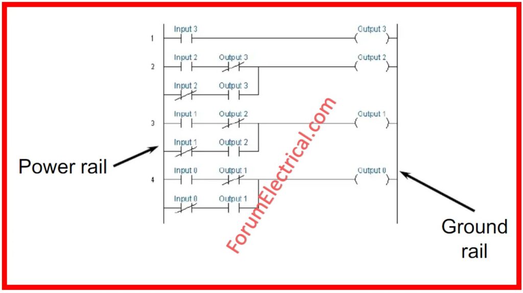
Ladder Logic Structure
Ladder logic diagrams are graphical programming languages that execute using real-time input.
- It has 2 vertical lines, known as rails; the left rail provides power to the circuit and then goes through each rung.
- Each rung contains switches and an output coil.
- Switches can do OR, AND, and NOT operations, and with these basic logic operations, we can create any programming logic in a PLC. A ladder logic diagram operates from left to right & top to bottom.
- When all of the conditions of a rung are met, the connected output coil is energized.
- Then it activates the real-world system, such as starting or stopping a motor.
- The PLC & control system scan and repeat this operation continually to ensure that the operating system is automated.
Ladder Logic Components
Here are several ladder logic components:
- Rail & Rung
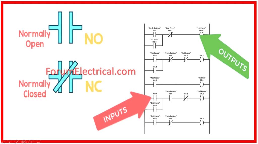
- Concept of NO/NC Switch
- Normally Open (NO)
- Normally Closed (NC)
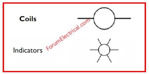
- Output/Coil
Rail & Rung
Vertical lines are termed rails, whereas horizontal lines are called rungs.
Concept of NO/NC Switch
NO (Normally Open) and NC (Normally Closed) are used to describe the state of current flow (or) contact in an electrical circuit, and they are also utilized in PLC ladder logic programming. These expressions indicate whether the switch is opened (or) closed.
Normally Open
When a typically open switch (or) contact is left unactuated, it remains open.
It shuts the circuit when pressed (or) engaged, letting current to flow.
In ladder logic diagrams, a typically open contact is depicted as an open gap that becomes a solid line once activated.
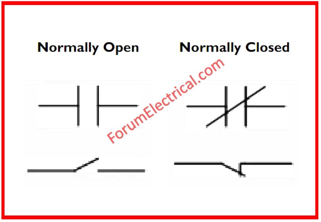
Normally Closed
When a normally closed switch or contact is not triggered, it remains closed.
The switch is activated, which opens the circuit and stops current flow.
In ladder logic diagrams, it is shown as a solid line that transforms into an open gap when activated.
Output/Coil
Output devices include motors, valves, indicators, and lights, but in LLD they are represented by a vertical line with a label that identifies the output device.
Working of Ladder Logic
- First, two rails are taken, followed by a rung. The rails will function here as a source of electrical current.
- The left rail is linked to the input switch, while the right rail is linked to the output coil. The switch & coils are interconnected via a wire.
- Next, incorporate an input switch that can be either normally open (NO) or normally closed (NC), depending on the desired logic to be established.
- Switches should be positioned on the left side rail. The quantity and positioning of the switch can change based on the logic being created.
- To develop this logic, we construct a truth table and based on its results, we determine the appropriate switch configuration. When the input is ‘0’, typically a normally open (NO) switch is used.
- However, it is also possible to use a normally closed (NC) switch in this condition, but it must be configured to be open or false.
- For an input of ‘1’, NC (Normally Closed) switches are typically used. However, it is also possible to utilize NO (Normally Open) switches, similar to the prior case.
- A connection should be made between the output coil and the right side rails.
Advantages of Ladder Logic
- A graphical representation of an electrical relay schematic for ease of understanding.
- The visual display of rungs minimizes maintenance.
- LLD enables real-time monitoring of the system condition, making it more reliable.
- LLDs are modular in nature, allowing for easy modification or expansion according to changes in-control process.
- LLD is widely recognized, as many engineers & technicians are already conversant with it.
Disadvantages of Ladder Logic
- LLD may encounter problems in complicated control systems due to a lack of knowledge in high-level programming languages.
- It is unsuitable for time-based operations or sequential problems.
- Proper documentation & version control might be difficult.
- It is not appropriate for data processing tasks.
Applications of Ladder Logic
Ladder logic programming is utilized in several industries, including:
- LLDs are frequently used in production control to regulate various machinery such as item sorting, quality control, and packaging.
- LLD controls pressure and chemical equilibrium in water treatment.
- It regulates HVAC (Heating, Ventilation, & Air Conditioning) in houses to maintain temperature, ventilation, and energy efficiency.
- LLDs are frequently employed in traffic control to preserve the time & sequence of traffic lights.
- To control the elevator, LLD can be utilized for level selection, door opening & closing, and so on.
- Ladder logic is also employed in food packaging & beverage manufacturing.
- LLDs regulate several components of chemical manufacture, such as temperature, pressure, mixing, & safety systems.
- LLD serve an essential function in storing renewable energy in the system.
Why are Ladder Diagrams used in PLC Programming?
Ladder diagrams are utilized to represent PLC logic equations graphically. They employ symbols to indicate
- Conditional,
- Input, And
- Output Expressions.
Ladder diagrams have similarities to relay control circuits & are commonly utilized because they are easier to write than text-based programming languages.
Earlier control system designers were familiar with relay logic control circuits, and ladder diagrams closely resembled them.
They preferred ladder diagrams for PLC programming over the text-based programming languages, such as
- C,
- BASIC,
- Pascal, and
- FORTRAN.
Factory maintenance personnel are already trained to interpret relay control circuits.
They can apply their expertise of relay control circuits to diagnose control system issues involving PLC programming and ladder diagrams.
The worldwide PLC programming standard IEC-61131 officially refers to a ladder diagram (LD).
However, terms like
- Ladder Diagram,
- Ladder Logic Diagram,
- Ladder Drawing,
- Ladder Control,
- Ladder Circuit,
- Control Logic Diagram, and
- Logic Diagram
are now used interchangeably to represent relay logic circuits and ladder logic programming.
How does Programmable Logic Control Ladder Work?
- Output Energize (OTE),
- Examine if Closed (XIC), and
- Examine if Open (XIO)
are the three most basic ladder logic PLC programming instructions.
Examine If Closed or XIC
This input command will check the supplied boolean bit to see whether the condition is True when the bit is set to 1/High.
If the bit is set to 0/Low, the command is going to evaluate the condition to False.
The remainder of the ladder logic rung shall be assessed and carried out if the condition is True.
Examine If Opened or XIO
This input command will check the supplied boolean bit to see whether the condition is True when the bit is set to 0/Low.
If the bit is set to 1/High, the command is going to assess the condition to False.
The remainder of the ladder logic rung shall be assessed and carried out if the condition is True.
Output Energize or OTE
This input instruction will set the bit’s associated XIC to True when it is on 1/High.
This input instruction will set the bit’s associated XIO to False when it is on 0/Low.
Basic Rung Analysis of Ladder Logic
Let’s examine the procedures the PLC uses to assess the conditions of a ladder logic rung:
Step 1: The “current” flows from the left to the right.
Step 2: The hypothetical current determines whether the condition is 0/False or 1/True when it comes into contact with an XIC instruction. If the XIC is False, no current will pass to the remaining elements in this rung. If the XIC is True, current will be able to flow.
Step 3: After then, the current is transferred to the subsequent command. Until the rung is finished, step 2 is repeated.
Step 4: Finally, the PLC moves on to the subsequent rung below and goes through similar actions once more.
Difference between an Electrical Schematic & a Ladder Diagram
Electrical Schematic vs Ladder Diagram
| Electrical Schematic | Ladder Diagram |
| In an electrical schematic, the control logic is represented by components. | In a ladder diagram, symbols are employed. |
| In an electrical schematic, control logic is executed in accordance with how an electrical circuit works. | In a ladder diagram, it is dependent upon how methodically the PLC scan is done. |
Series & Parallel Connection in Ladder Diagram
In a ladder diagram, we can link contacts (usually open and normally closed) in parallel or series. Coils are only arranged in parallel. However, some ladder programming software provides specific instructions for the coil series connection.


