
What is Brake Test of a DC Motor?
The brake test is a direct testing method utilized to determine the efficiency of a DC motor. In this test, brakes are applied to a water-cooled pulley positioned on the motor shaft based on the machine’s rating.
- What is Brake Test of a DC Motor?
- How the Test is Performed?
- Brake Test
- Scope
- Name Plate Details
- Equipment Details
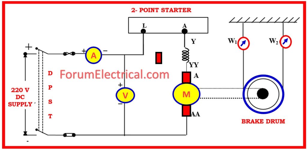
- Circuit Diagram of Brake Test of DC Series Motor
- Procedure
- Safety Measures
- Tabular Observations
- Graphical Representation
- Advantages of Brake Test of DC Motor
- Disadvantages of Brake Test of DC Motor
- Frequently Asked Questions (FAQ)
- Direct Method,
- Indirect Method, and
- Regenerative Method
are the three distinct approaches that can be utilized in the testing to evaluate DC Machines.
The Direct Method of testing a DC Machine, which is sometimes referred to as the Brake Test (if it is performed on a DC Motor).
For DC machines of a smaller size, the direct technique is appropriate.
The Direct Method involves putting the DC machine through its rated load, which results in the complete loss of all of the power to be output.
The efficiency of a DC machine can be determined by what the ratio of the output power to input power is.
When a DC generator is used, the power that is produced is lost in the resistor.
How the Test is Performed?
Wooden blocks holding the pulley hold the brake rope in place. One end of the rope is attached to the ground by spring balance ‘B’, while another end is attached to a suspended weight ‘W1‘.
Now, the motor is permitted to run under this condition, and the load on the motor is modified so that it delivers full-load current by adding (or) removing weights from suspended weight ‘W1‘. Let the reading on the spring balance ‘B’ be ‘W2‘.
While raising the load, the load is increased in a step-by-step manner till full-load condition is obtained, and for each step, various values of the voltmeter, ammeter, suspension weights (W1 and W2), and speed of the motor are documented, and the efficiency of the rotor can be estimated as follows:
The net draw on rope due to friction at pulley is as follows:
= (W1-W2) kg wt
= 9.81 (W1-W2) Newton
The motor produces shaft torque Tsh, which is given by,
Tsh = (W1-W2) R kg-mt
Tsh = 9.81 (W1-W2) R N-m
Where
R – Pulley Radius
Motor Output Power is expressed as,
Pout = Tsh x ω (watts)
Pout = (2Π x 9.81/60) (W1-W2) R N watts
Pout = 1.027 (W1-W2) R N watts
When,
V – Voltage
I – Full load current of motor
Pin = VI (watts)
The efficiency is given by,
Motor Efficiency (η) = (Motor Output Power/Motor Input Power) x 100
η = {[1.027 (W1-W2) R N]/VI} x 100
Brake Test
Scope
It is necessary to get the performance features of the DC series motor.
Name Plate Details
| Voltage | |
| Current | |
| Output | |
| Field | |
| RPM |
Equipment Details
| S.No | Equipment | Type/Parameter | Range | Quantity |
| 1 | Ammeter | |||
| 2 | Voltmeter | |||
| 3 | Rheostat | |||
| 4 | Tachometer | |||
| 5 | Connecting wires |
Circuit Diagram of Brake Test of DC Series Motor
Procedure
- Connect the circuit in accordance with the circuit diagram.
- To ensure that there is no load on pulley, check that the belt that is attached to it is not clogged.
- The DPST switch should be closed, and the motor should be started slowly utilizing the starter.
- Utilizing the field rheostat, adjust field current so that the motor operates at the speed that is specified for it.
- Pulley load should be applied gradually and in stages, with the belt being tightened around the pulley.
- Determine the speed at each step, as well as the readings from the ammeter & voltmeter that are attached to the motor, as well as the readings from the two spring balances.
- Carry on with the experiment until the motor is operating at its maximum capacity.
- Turn off the supply after removing the load up to fifty percent of its full capacity.
- Create a table with the observations.
Safety Measures
- The motor field rheostat must be maintained in the position with the least amount of resistance.
- A condition known as minimum load should be present in the motor at the time that it is started.
- Through the use of water, the pulley can be cooled while experiment is being carried out.
- If you are going to measure the radius of pulley, you need to take into consideration the effective radius.
Tabular Observations
S.No | Voltage (V) | Current (I) | Speed (N) | Spring Balance Readings | Torque (T) | Output 2πNT/60 (watts) | Input V x I | %η | ||
| W1 | W2 | W1~W2 | ||||||||
| 1 | ||||||||||
| 2 | ||||||||||
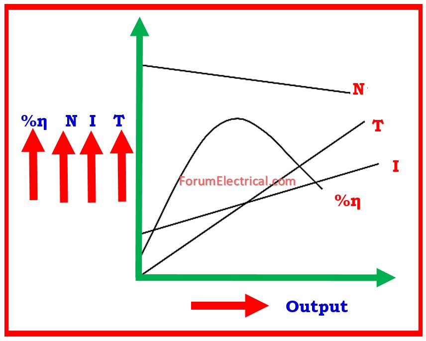
Graphical Representation
Advantages of Brake Test of DC Motor
- Test does not require any more equipment. Therefore, it diminishes both the cost and the energy.
- This technique is really easy to understand.
- This is a very convenient option for smaller motors.
Disadvantages of Brake Test of DC Motor
- Only for small motors are tested. Brake heat is hard to dissipate in large motors.
- Spring balancing faults causes motor output to be inaccurately estimated, which affects DC motor internal losses and efficiency.
- In DC series motors, the brake must be tight to prevent the motor from reaching unsafe speeds and causing damage.
Frequently Asked Questions (FAQ)
1). Why does a series motor never start in a no-load condition?
It is not recommended to start a DC series motor without any load because
The armature and field winding of a series motor are linked in series. This indicates that the armature current determines the field current.
A weak magnetic field results from the extremely low armature current with no load.
Because speed (N) and flux (Φ) are inversely proportional
i.e., N α1/Φ
a weak flow results in an excessively high speed.
Due to centrifugal forces, this may result in severe vibrations, mechanical damage, or possibly the motor’s demise.
To maintain speed within a safe range, a series motor needs to constantly have a load prior to starting.
2). What are the applications of a DC Series Motor?
DC series motors are utilized in applications that demand high starting torque & variable speed.
Some common applications are:
- Electric locomotives provide strong torque & variable speed control (VSD).
- Traction systems are utilized in electric trains, trams, & trolley buses.
- Cranes and hoists are designed to raise big objects with a high starting torque.
- Elevators and lifts require a significant beginning force.
- Electric cars (EVs) – in older EV designs, torque is important.
- Steel rolling mills are used for high-powered machinery.
- Conveyors and industrial machinery are used to transfer huge goods.
3). Why the series field winding having thick and less turns?
The DC series field winding uses thicker wire and fewer turns because:
- It is in series with armature, it carries the entire armature current, which is enormous. A thicker wire is required to carry this current without overheating.
- A thicker conductor lowers resistance & prevents power loss.
- Stronger magnetic field with the fewer turns. Because the current is high, fewer turns are required to produce the desired magnetic field.
- More turns would increase winding resistance, resulting in undesirable voltage drops and reduced motor efficiency.
Thus, thicker wire with fewer turns assures efficient operation while retaining high torque output in a DC series motor.


