
Equipment connected to electric power systems for the purpose of monitoring and identifying conditions that are undesirable and unacceptable and for the purpose of bringing about corrective measures.
The protective system that falls under this category include:
- Lightning arrestors,
- Surge protectors,
- Fuses, and
- Relays
- Circuit Breakers,
- Reclosers, and so on.
It is, however, important to note that at certain times disruptions in the regular function of a power system take place.
These may be due to lightning, wind, or snow, falling trees, animal touches or bites, accidental contacts with live parts by careless drivers, workers, personnel engaged in plant maintenance or other people; or switching spurts, load or resonance or equipment failures.
Protective devices must therefore be connected to power systems in order to maintain the continuity of electric supply, to minimize the risk of people and properties, and to minimize the extent to which troubles affect equipment when such situations occur.
It is always necessary to apply protective devices in proportion with the amount of protection needed or assumed for the given system.
Why is Protective Device Testing done?
Protection systems are vital elements for the secure and efficient functioning of the contemporary electricity power systems.
Effective protection devices assist in the protection of the system and integrity of property to prevent them from getting damaged.
Both
- Protective relays and
- Recloser controls
must be tested in their life-cycle during the design, production, commissioning, and periodical maintenance during utilizing.
They affirm that the test equipment that they use is suitable for those various phases of the life cycle and for any surroundings.
We provide you outstanding testing solutions which are under constant improvement to meet the rising expectations of your systems.
What is done during Protective Device Testing?
Protective device testing involves the following activities:

Lightning protection is a way in which one can shield the equipment, the facilities and the people around in case of nearby or direct incidents of lightning. Whereas, surge protection offers protection of the equipment from consequences of distant strikes or other abnormal power phenomena.
Five fundamental methods are used in the testing of protection devices.
1). Clamping Voltage Test
2). Surge Withstand Test
3). Energy Absorption Test
4). Combination Wave Test
5). Duty Cycle (Flammability) Test
1). Clamping Voltage Test
In any transient, the SPD resistance switches from a very high standby mode to a very low conduction mode.
It is coupled and grounded at a specific level to shield most vulnerable, high-frequency, electronic circuits from short and transfer the energy of the transient to the common ground.
The current impulses have normalized forms, where one of the most used is 8/20 us, defined by the standards IEC 61643-1 and IEC 61180-1.
2). Surge Withstand Test
The withstand tests which are called surge withstand tests are in fact aimed at checking the maximum possible peak current that can be carried by varistors.
The SLA capacity for withstanding surge voltage increases with an increase in the size, particularly the disk diameter of the varistor.
Impulse voltage tests are much more demanding in terms of energy in kilo amperes in range of tens than the clamping voltage tests for different types of the equipment.
3). Energy Absorption Test
High impulse loads are mainly caused by starting and operating poly-phase motors and electromagnetic transformers.
Absorbed energy in an SPD is defined as the integral of the current through or the voltage across an SPD.

Short surge currents with spikes of medium or big value in a scale of microseconds are necessary if the aim is to test the maximum amount of energy that an SPD is capable of absorbing.
A rectangular wave of 2ms duration is used, for some cases instead of the double exponential waveforms.
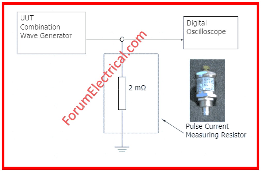
4). Combination Wave Test
Surge events can be caused by
- Lightning activities,
- Switching transitions and other related occurrences in power systems including protection devices.
By way of consequence, a surge will depend on the propagation path taken so that the impulses arising from the same occurrence will have different forms, based on where the measurement is taken from.
“Combination Wave Generators (CWG)” liberate a surge event in power lines near or inside the building.
5). Duty Cycle (Flammability) Test
A number of pulse episodes are initiated across the varistor with a view of measuring the maximum rated dissipation on the part.
If the power over the maximum rated dissipation condition is allowed to flow through the unit, the protection device will be destroyed.
Flammability risk could be noted. The 8/20us current impulse signal is then added to the mains voltage supply.
How protective devices testing is conducted?
The basic devices also are capable of knowing about
- Low-voltage breakers
- Relays
- Directional and Power Relays
- Differential Relays
- Fuses
- Protective relays,
- Breaker trip devices and
- Surge suppressors and
also know how they differ and for what they are used for applications.
Another danger for relay testers is that they tend to incorporate spare outputs, displays and or LEDs for their pickup and timing tests and then disregard the in-service output logic feeling they are using the same elements in their test equations as are in the final logic.
Depending on the protective device the tests might vary accordingly.

Motor Management Systems
Electromechanical and solid state relays were previously tested similarly where there was no microprocessor relay.
This was a consistent methodology, which enabled the individual segments of the relay to be regulated and, by extension, tested.
But when microprocessor relays appeared, products high and low, most carried on with this approach and tested individual elements within the relay while others sought other means of testing.
Developing automated testing procedures for the microprocessor relays may be classified into 3 categories:
- Element testing,
- Functional testing, and
- Black box testing.
Thus, the black box testing method is quite sufficient as far as NERC compliance is concerned.
Regardless of whether the organization is using functional or black box testing, dynamic testing software is the natural way to carry it out.
Dynamic tests compel the relaying test sets to perform in a series of established sequences referred to as states for example pre-fault, fault and post-fault.
Element testing of microprocessor relays is expected to reduce, primarily due to the indicated weaknesses associated with the application.
Advantages
- Standard control unit, minimizes the training of users
- A precise measurement system provides the information about the SPD.
- The use of integrating test facilities with current engineering structures helps in cutting down the engineering expense.
- Results of the assessment of the passing / failing factor on individual samples to increase production rates
- Very highly automated, operator loading is kept to a minimum.
- Save operator time with the mentioned automatic test routines and the test report facility
- These modules are easily integratable into a full test suite.
- There is provision of optimum reliability and system up time.


