
What is Primary Injection Testing?
Primary injection testing is an integrated method for assessing the performance of the solid-state and electromechanical trip devices.
- What is Primary Injection Testing?
- What is Secondary Injection Testing?
- Properties of Primary Injection Testing
- Why do we need Primary Injection Test?
- Primary Injection Testing Procedure
- Testing Equipment
- Test Configuration Essentials
- Procedure
- 1). CT Ratio Test
- 2). CT Polarity Test
- 3). Relay Element Testing
- 4). Protection Scheme Logic (PSL) Testing
- Types of Primary Injection Tests
- 1). Power Transformers (Thru-Fault Testing)
- 2). Relay Functional Testing
- 3). Switchgear & Busbar Verification
- 4). Low Voltage Breakers
- 5). Heat Runs
- Specific Tests during Primary Injection Testing (PIT)
- 1). Stability Test
- 2). Loose Connection Detection
- 3). Core Identification
- 4). Single-Point Grounding Check
- Advantages of Primary Injection Testing (PIT)
- Disadvantages of Primary Injection Testing (PIT)
- Difference between Primary Injection Testing and Secondary Injection Testing
- Primary Injection Testing vs. Secondary Injection Testing
- Conclusion
This type of relay injection testing entails injecting the required current directly into a system while evaluating all sensors, wiring, and the circuit breaker’s current conduction channel.
Because of its intricacy, primary injection testing should be performed by a specialist.
It is especially important for circuit breakers used in sensitive operations or engineered safety systems, where dependability is key.
This testing approach is also frequently utilized throughout the commissioning phase, usually in conjunction with the secondary injection testing.
A disadvantage of primary injection testing is that it may fail to detect sensor wiring & polarity issues until all 3 phases of the breaker are tested concurrently.
Despite this drawback, the primary injection testing is essential for electrical system stability and functioning.
What is Secondary Injection Testing?
Secondary injection testing is an important procedure in the area of relay injection testing, particularly during scheduled maintenance for the solid-state trip units.
Secondary injection testing, as opposed to primary injection testing, is ineffective for electromechanical trip devices.
This method use a secondary injection test kit to replicate the three-phase currents that commonly pass through the trip unit while the circuit breaker is closed & not carrying current via its main poles.
Secondary injection testing can find sensor wiring and polarity issues that the primary injection testing ignored.
However, it only checks the unit’s logic and wiring, leaving the other current-carrying components untouched.
Secondary injection testing is suitable for normal maintenance but may not be sufficient for advanced systems.
It is often used with primary injection testing to assess circuit breaker performance throughout the year.
Properties of Primary Injection Testing
- For thermal magnetic & electronic breakers, it is possible to accomplish this test.
- Takes a lot of time.
- The trip unit, CT wiring, and CT full breaker should be tested.
- For the test to be done, further expertise is required.
- Equipment is heavy & therefore less portable.
- It is more expensive.

Why do we need Primary Injection Test?
The primary and secondary windings of the current transformer, the relay coils, the trip & alarm circuits & all the wiring in between are all checked during this type of test.
Because wire can be left unaffected, the risk of current transformers becoming open-circuited can be avoided.
Additionally, switching in current transformer (CT) (or) relay circuits is typically unnecessary.
The primary concern with this type of testing is how much time and money they need to set up.
There is an increasing number of concern about the need of accurate wiring and installation designs, accurate implementation of the installation according to the drawings, and successful completion of secondary injection testing.
The primary injection tests might not be necessary in this case.
However, faults with wiring between VTs/CTs & relays (or) with the polarity of VTs/CTs, could go undetected until spurious tripping happens in service, or even worse, when they fail to trip when a fault is present.
In digital or numerical relay applications, their built-in current & voltage measurement & display capabilities allow relay input values to be compared to other reliable sources, reducing this risk.
By temporarily splitting the relay trip outputs, unwanted trips can be averted and many connection/wiring faults detected.
However, primary injection testing is the only technique that can demonstrate that a complete protection mechanism was installed and is operating correctly.
Once the secondary injection tests have revealed that all other equipment in the protection system is satisfactory, the next step is to conduct primary injection testing.
This can verify that VTs, CTs, and wiring are the only issues.
Primary Injection Testing Procedure
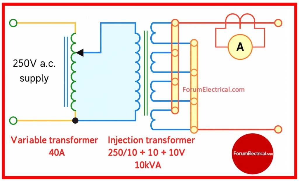
Testing Equipment
- Conventional Injection Transformers
- Modern PC-Controlled Test Sets
- Test Windings (if available)
Test Configuration Essentials
- To minimize voltage drops during testing, use short, low-impedance cords.
- Parallel connections provide sufficient ampacity.
- Appropriately rated input breakers.
- Stab sets for pull-out circuit breakers.
Procedure
1). CT Ratio Test
This test ensures that the current transformer (CT) is running at the proper ratio. A known current is injected via the primary conductor, and two readings are obtained:
- One from the test set ammeter (A1), which measures the primary current &
- Another from either a secondary ammeter (A2) (or) the relay’s display, which shows the secondary output.
The ratio between these 2 values should be similar to the CT’s nameplate ratio.
Significant deviations may indicate CT saturation, open circuits (or) fault connections.
2). CT Polarity Test
This is an important test for protection schemes that use directional, differential, (or) earth fault relays as improper polarity might result in protection problems (or) false trips.
The residual current is measured by injecting current in phase on one side of CT & shorting the other.
If CTs are connected correctly, only a small current will be detected.
However, if they are inverted, the residual current can reach twice the nominal value.
Repeat this test for each phase combination to verify CT wiring arrangement.
3). Relay Element Testing
This process tests each protection element: overcurrent, earth fault (or) differential by injecting appropriate fault-level currents into the system.
These tests demonstrate that the relay responds correctly to simulated fault events and launches a trip within the required time.
Many of these verifications can be performed via numerical relays’ internal display (or) communication ports, avoiding the need for human checks.
However, manual current injection remains the most reliable method of ensuring that settings are correctly implemented & functional.
4). Protection Scheme Logic (PSL) Testing
Modern digital and numerical relays contain embedded programmable scheme logic (PSL), which controls the relay’s response based on the input conditions.
During PSL testing, the logic is validated with software tools that replicate different conditions such as
- Breaker open/close status,
- Interlocks & other digital inputs.
These tests demonstrate that all logical sequences including breaker failure protection (or) inter-tripping, respond correctly to stimuli. PSL is typically programmed using IEC 61131 standard programming languages, such as ladder logic (or) Boolean logic.
Types of Primary Injection Tests
1). Power Transformers (Thru-Fault Testing)
This test includes introducing 3-phase power into a transformer that has its windings shorted.
It minimize actual fault conditions ensuring that CTs on the both the high & low voltage sides are sending the correct signals to the protection relays.
It also ensures that differential protection settings are properly coordinated and that any wrong CT polarity is identified.
2). Relay Functional Testing
By injecting fault-level currents, this test determines if the protection relay detects the problem and transmits a trip signal within the specified operating period. This is important for determining
- Time-current coordination,
- Pickup values, and
- Delay settings.
3). Switchgear & Busbar Verification
High current is provided to busbar (or) switchgear circuits to ensure that the protection relays receive the right amplitude & phase of current from their respective CT.
This is frequently performed at commissioning or during maintenance to ensure the reliability of
- CT wiring,
- Inter-panel connections &
- Zone-selective interlocking.
4). Low Voltage Breakers
This test checks low-voltage circuit breakers’ short-circuit and overload conditions.
A fault-level current is injected for a certain time to see if the breaker trips as planned.
The trip curve generated is compared to the manufacturer’s requirements to check conformity.
5). Heat Runs
A heat run involves injecting continuous high current for extended periods of time to assess the thermal performance of the
- Electrical junctions,
- Conductors and
- Switchgear.
This type of testing finds
- Hotspots,
- Excessive temperature rise and
- Other thermal issues that may not be visible in short-term functional tests.
Specific Tests during Primary Injection Testing (PIT)
1). Stability Test
Stability testing guarantees CT polarity & connection accuracy in the differential protection schemes. If CT polarities are swapped during a PIT, a differential relay can identify inappropriate differential current when there is no fault.

Errors can be spotted and fixed before the system is turned on by monitoring the relay’s differential current reading during the primary current flow.
A zero (or) near-zero differential current indicates appropriate polarity.
2). Loose Connection Detection
When rated current flows through the circuit, inadequate or loose connections might cause sparking, localized heating (or) voltage drop.
These faults, which become obvious during PIT may be difficult to detect using only low current (or) continuity checks.
Identifying and rectifying them helps to prevent future failures & ensures the protection system’s long-term reliability.
3). Core Identification
When a CT has many cores (for metering, protection or backup protection), knowing which core feeds which circuit is essential.
During PIT, each core is sequentially shorted at the CT terminal, and the resulting current loss is monitored by the attached relays or meters.
This method ensures that no cores are mixed up and that each function receives current from appropriate winding.
4). Single-Point Grounding Check
Current transformer secondary circuits must be grounded at one point to prevent currents from flowing and protect personnel.
During this test, current is injected across one phase & the earth & secondary current is measured over the entire CT circuit.
The presence and quantity of current in each path may assist to confirm proper grounding & identify any unintentional (or) duplicate grounds.
Advantages of Primary Injection Testing (PIT)
- Validating the complete protection mechanism from source to trip.
- Verifies CT polarity & proper installation.
- Identifies wiring problems, weak connections, and configuration discrepancies.
- Suitable for commissioning new installations & substantial retrofits.
Disadvantages of Primary Injection Testing (PIT)
- Time-consuming and resource-demanding.
- Test equipment must be hefty and high-current.
- Secondary testing is less hard to set up and execute.
Difference between Primary Injection Testing and Secondary Injection Testing
Primary Injection Testing vs. Secondary Injection Testing
| Feature | Primary Injection Testing (PIT) | Secondary Injection Testing (SIT) |
| Test Scope | End-to-end system testing includes CT primary, CT secondary, relay inputs, trip circuits & breaker coils. | Isolates the relay from the system, testing only its internal logic and trip output with synthetic signals. |
| Test Load | High current (up to several kA) simulates real failure conditions via actual system wiring. | Low current (milliamps to a few amps) is fed into the relay’s secondary input terminals. |
| Test Equipment | Heavy-duty injection transformers or new high-current injection kits are required; this makes the system more power-intensive and bulky. | It employs lightweight, small relay test units with signal generating, ramping & communication interfaces. |
| Accuracy of Test | Highly accurate – checks CT burden, wiring integrity, relay responsiveness, and breaker trip behavior in real time. | Limits logic & timing checks within the relay; does not validate CT wiring or breaker coil activity. |
| Use Case | Ideally suited for commissioning, through-fault testing, protection scheme verification, and trip time validation. | Ideal for routine maintenance, functional relay testing, timing verification, and firmware upgrades. |
| System Dependency | The system must be de-energized before the test; no energization is permitted during the test. | Can often be done while the system is turned on, especially when relay terminals are isolated. |
| Complexity | High – necessitates various configurations, connections, monitoring of the current paths, and coordination among multiple personnel. | Moderate – normally handled by a single test engineer who follows basic safety precautions. |
| Setup Time | Heavy cables, parallel conductors, CT circuit verification & stab/panel access all contribute to the increased length. | Faster – minimum wiring & quick configuration for utilizing test software. |
| Trip Output Validation | Verifies genuine breaker tripping by energizing the coil and monitoring the auxiliary contacts. | Simulates trip signals, but may not activate the breaker if wired in live or dry contact logic. |
| Cost & Resource Requirements | Expensive – high-current test kits, additional staff, power supplies, and downtime costs. | Cost-effective – smaller kits, less personnel, appropriate for routine field testing. |
| Risk Level | Higher – Due to the high currents, there is a risk of an arc flash if connections are inadequate or equipment malfunctions. | Lower – test voltages & currents are low, with little possibility of physical or equipment damage. |
| Regulatory Requirement | Electric utilities frequently require first-time commissioning, particularly for substations, transformers & switchgear. | Widely utilized for annual (or) biannual relay maintenance and firmware checking. |
Conclusion
Primary injection testing is the thorough circuit breaker test. It verifies the entire protection chain of a circuit breaker.
The current flows through the circuit breaker’s pole(s), validating the current-carrying channel.
The current sensors & wires are inspected. The trip unit’s logic has been verified. The breaker’s mechanism is also checked.
As a result, it is possible to conclude that the circuit breaker has been thoroughly tested.