In a balanced 3-phase Y-connected (star) system the neutral conductor carries no current since the three phase currents are equal in magnitude and displaced by 120 electrical degrees that is causing their vector sum to be zero.
However under unbalanced conditions such as single line-to-ground faults, unequal single-phase loading (or) the presence of triplen harmonics that the neutral conductor does carry current.
An extremely useful result of symmetrical component theory is that this neutral current is always exactly three times the zero-sequence current present in the system.
This relationship
expressed as IN = 3I0 is fundamental to
- Protective relaying,
- Fault analysis,
- Transformer design and
- Power quality studies.
This post explains the theoretical basis of this relationship that derives it step by step and discusses its practical significance.
Symmetrical Components
The method of symmetrical components, introduced by Charles LeGeyt Fortescue in 1918 allows any unbalanced set of three-phase phasors to be resolved into 3 balanced sets:
- Positive-sequence components,
- Negative-sequence components and
- Zero-sequence components.
Positive-Sequence Components
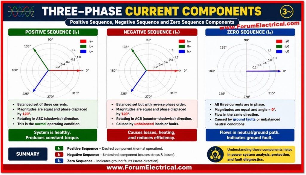
The positive-sequence set has the same phase rotation as the original system (a-b-c).
Negative-Sequence Components
The negative-sequence set has the opposite rotation (a-c-b).
Zero-Sequence Components
The zero-sequence set consists of three phasors that are equal in magnitude & in phase with one another (no rotation at all).
Using the complex operator a = 1∠120° (so that a² = 1∠240° and 1 + a + a² = 0) the three actual line currents can be expressed in terms of their sequence components as shown below:
| Phase Current | Symmetrical-Component Expression | Sequence Sense |
| Ia | I0 + I1 + I2 | Zero + Positive + Negative |
| Ib | I0 + a²I1 + aI2 | a = 1∠120° |
| Ic | I0 + aI1 + a²I2 | a² = 1∠240° |
Deriving the Neutral Current Expression
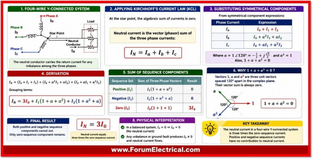
In a four-wire Y-connected system, the neutral conductor carries the return current for any imbalance among the three phases.
By Kirchhoff’s Current Law applied at the star point, the neutral current is simply the vector (phasor) sum of the three phase currents flowing back through the neutral:
IN = Ia + Ib + Ic
Substituting the symmetrical component expressions for Ia, Ib and Ic from the table above gives:
IN = (I0 + I1 + I2) + (I0 + a²I1 + aI2) + (I0 + aI1 + a²I2)
Grouping terms according to their sequence component (collecting all I0 terms together, all I1 terms together and all I2 terms together) gives:
IN = 3I0 + I1(1 + a + a²) + I2(1 + a² + a)
This grouping is the crux of the derivation and it is illustrated numerically below:
| Sequence Set | Sum of Three Phase Vectors |
| Positive (I1) | I1(1 + a² + a) = 0 |
| Negative (I2) | I2(1 + a + a²) = 0 |
| Zero (I0) | I0(1 + 1 + 1) = 3I0 |
The identity 1 + a + a² = 0 is a basic algebraic property of the cube-root-of-unity operator a, & it holds because a, a² and 1 are three unit vectors spaced exactly 120° apart and their vector sum is always zero regardless of the magnitude of the current multiplying them.
Consequently both the positive-sequence term I1(1 + a + a²) and the negative-sequence term I2(1 + a² + a) vanish completely leaving only the zero-sequence contribution:
IN = 3I0
Physical Interpretation
This result provides a clear physical theory.
Positive- and negative-sequence currents are by definition, balanced three-phase sets even though they may rotate in opposite directions and each set still consists of three equal-magnitude phasors 120° apart.
Just as in a perfectly balanced load, the vector sum of any balanced three-phase set is zero, so neither the positive nor the negative sequence currents can generate any net flow in the neutral.
Only the zero-sequence set breaks this symmetry: all three zero-sequence phasors point in the same direction at the same instant and so instead of cancelling they add directly.
Since there are three identical zero-sequence components, one for each phase, their sum is three times the value of a single one.
Put differently, zero-sequence current is the current that is common and in-phase across all three lines as per theory.
When such a common component exists it cannot return via the other 2 phase conductors because they carry the same in-phase component simultaneously.
The only path available for this common current is the neutral conductor (or the earth in a grounded system without a physical neutral wire) which is the only reason the neutral is sized to carry it and why IN = 3I0 rather than simply I0.
Practical Significance
The relationship IN = 3I0 is important in several important areas of power system engineering:
Ground-Fault Protection
Zero-sequence (residual) relays and ground-fault relays measure 3I0 either directly from a neutral current transformer (or) from the residual connection of three phase CTs to detect single line-to-ground & other ground-involved faults.
Neutral and Grounding Conductor Sizing
Because the neutral should carry 3I0 under unbalanced (or) fault conditions its ampacity & the grounding system design should account for this tripling effect particularly in systems with significant single-phase (or) nonlinear loading.
Triplen Harmonics
The 3rd, 9th, 15th and other odd multiples of the 3rd harmonic (triplen harmonics) generated by nonlinear loads such as computers, LED drivers and variable-frequency drives behave as zero-sequence quantities.
In a Y-connected system with a neutral these harmonic currents add arithmetically in the neutral rather than cancelling which can cause the neutral conductor to carry more current than any individual phase.
Transformer Design
Delta-Y transformers are frequently employed since the delta winding creates a closed path that captures zero-sequence (and thus triplen-harmonic) current limiting it from spreading farther into the system and lowering neutral load downstream.
Fault Current Calculations
In short circuit studies, the ground-fault current at a Y-grounded point is calculated using the sequence networks and the factor of 3 applied to I0 is essential for obtaining the correct magnitude of fault current seen by the protective devices.
Illustration
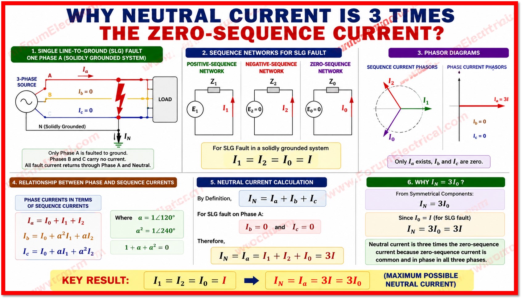
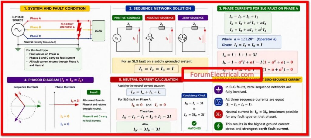
Consider a single line-to-ground fault on phase A of a solidly grounded system where the positive- sequence, negative- sequence and zero-sequence fault currents are found (from the sequence network solution) to be equal, that is
I1 = I2 = I0 = I.
For this fault type, phases B and C carry no fault current while all of the fault current returns through phase A and the neutral.
Applying
IN = Ia + Ib + Ic
and noting that Ib and Ic are zero for this fault type gives
IN = Ia = I1 + I2 + I0 = 3I
This matches exactly with IN = 3I0 = 3I confirming the consistency of the symmetrical-component result with direct phasor addition and it also shows why single line-to-ground faults generate the largest possible zero-sequence current of any fault type on that phase.
Conclusion
The factor of 3 linking neutral current to zero-sequence current arises directly from the mathematics of symmetrical components:
- Positive-symmetrical components and
- Negative- symmetrical components form balanced sets
that always sum to zero while the three zero-sequence components are identical and in-phase so they add rather than cancel.
This simple but powerful relationship, IN = 3I0, is one of the most frequently applied results in power system protection and analysis that is forming the basis of
- Ground-fault relaying schemes,
- Neutral conductor sizing rules and
- Understanding of triplen-harmonic behavior
in modern power systems with widespread nonlinear loading.

