
Filters are one type of device used in signal processing to allow required frequency components while removing unwanted frequency components.
- What is Band-Pass Filter?
- Band Pass Filter Circuit (BPF Ciruit)
- Types of Band Pass Filters
- Band Pass Filter Transfer Function
- Band Pass Filter Cut-off Frequency
- Band Pass Filter – Bode Plot (or) Frequency Response
- The Ideal Band Pass Filter
- Equation for a Band Pass Filter
- Advantages of a Band Pass Filter
- Disadvantages of a Band Pass filter
- Applications of Band Pass Filters
Filtering is defined as reducing interfacing signal background noise by removing some frequencies.
The filter’s circuit can be used to combine the LPF and HPF properties into a single filter known as a band pass filter.
Filters are classified as analog/digital, active/passive, linear/nonlinear, and time-variant/time invariant.
This article provides an overview of band pass filters and their applications.
What is Band-Pass Filter?
A band pass filter, also known as a BPF or pass band filter, is a device that allows (enables) frequencies within a specific frequency range while rejecting (attenuating) frequencies outside of that range.
The low pass filter isolates signals with frequencies greater than the cut-off frequency.
The high pass filter, on the other hand, is used to isolate signals with frequencies lower than the cut-off frequency.
The cascade (sequence) connection of high pass and low pass filters creates another filter that allows the signal with a specific frequency range or band and attenuates the signals that are outside of this band.
Band Pass Filter is the name given to this type of filter.
Band Pass Filter Circuit (BPF Ciruit)
The RLC circuit shown below is the best illustration of a band pass filter circuit.
This filter can also be created by combining an LPF and an HPF. Bandpass in BPF represents a type of filter or filtering procedure.
It should be distinguished from passband, which refers to the actual section of the influenced spectrum. Because an idyllic bandpass filter lacks gain and attenuation, it has a completely level passband.
All frequencies outside the passband will be completely attenuated.
In practise, the bandpass filter is not perfect because it does not completely attenuate all frequencies outside of the preferred frequency range.
There is a section (segment) just outside the proposed pass band where frequencies are attenuated but not discarded, which is known as the filter roll-off, and it is usually specified in dB (decibel) of attenuation for every octave or decade of frequency.
In general, the filter design seeks to make the roll-off as thin as possible, allowing the filter to perform the proposed design.
This is frequently accomplished at the expense of passband ripple, rather than stopband ripple.
The filter bandwidth is defined as the difference between the upper and lower frequencies.
A form factor of 2:1 at 20/2 dB means that the bandwidth calculated among the frequencies at 20 dB (decibel) attenuation is twice that calculated among the frequencies at 2 dB attenuation.
Optical BPFs are widely used in the photography and theatrical lighting. These filters use the outline of a clear coloured film instead of a sheet.
Types of Band Pass Filters
Band pass filter circuits emerge in a variety of shapes and sizes.
They are
- Active Band Pass Filter
- Passive Band Pass Filter
- RLC Band Pass Filter
- Wide Band Pass Filter
- Narrow Band Pass Filter
1). Active Band Pass Filter
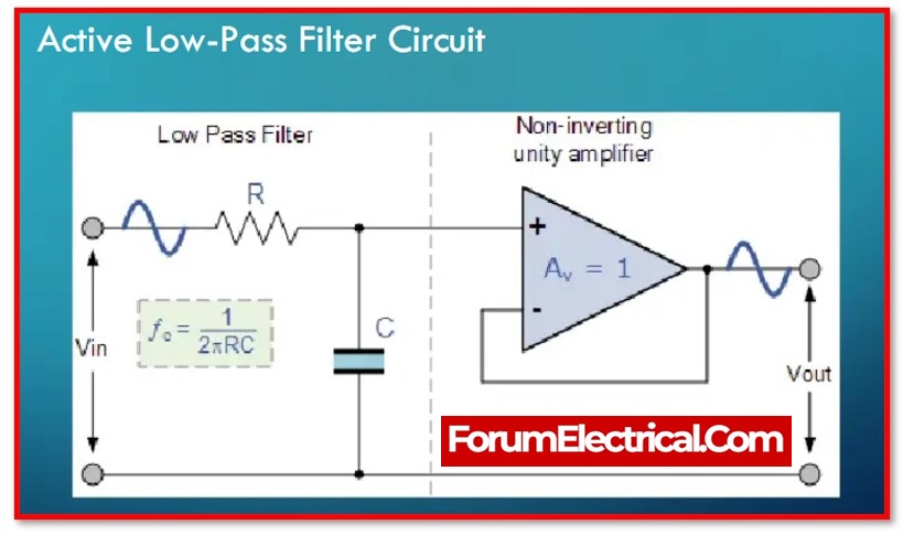
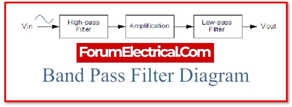
The active band pass filter is a cascade connection of the amplifying component and the high pass and low pass filters.
The Active Band Pass Filter consists of three sections. A high pass filter is the first part. The op-amp is then utilised for amplification. The low pass filter is the circuit’s final component.
2). Passive Band Pass Filter
The passive filter used passive components including such resistors, capacitors, and inductors.As a result, the passive band pass filter also employs passive components and does not rely on an op-amp for amplification. As a result, unlike an active band pass filter, a passive band pass filter lacks amplification.
A passive band pass filter is made up of passive high pass & passive low pass filters.
The passive high pass filter is implemented in the first half of the circuit. The second half is dedicated to the passive low pass filter.
3). RLC Band Pass Filter
RLC stands for resistor, inductor, and capacitor. This is also another passive band pass filter.
The RLC band pass filter has two circuit configurations based on the RLC connection. In the 1st configuration, the series LC circuit is connected in series with the load resistor. The 2nd configuration is a parallel LC circuit connected in parallel with a load resistor.
The bandwidth of the series and parallel RLC band pass filters is shown in the equations below.
Bandwidth of a series RLC filter
Δω = RL/L
The corner frequency equation is the same for both configurations, and it is
Bandwidth of a parallel RLC filter
Δω= 1/RLC
4). Wide Band Pass Filter
It can be divided into two types of filters based on their bandwidth:
- Wide bandpass filters and
- Narrow bandpass filters.
A wide pass filter is one with a Q-factor less than 10. The bandwidth of the wide bandpass filter is large, as the name indicated.
The high pass and low pass filters, like the passive band pass filter, are distinct sections of this type of filter.Both filters are passive in this circumstance.
An active high pass & an active low pass filter can be used in another circuit configuration.
The first half of this filter’s circuit represents an active high pass filter, while the second half represents an active low pass filter.
Because of the various components of filters, it is simple to design a circuit with a wide bandwidth.
5). Narrow Band Pass Filter
A band pass filter with a quality factor of more than ten. This filter has a limited bandwidth. As a result, it allows for a signal with a limited frequency range. It has received a lot of feedback. Only one op-amp is used in this band pass filter.
Since there are two feedback paths, this band pass filter is also called as a multiple feedback filter.
The op-amp is used (utilised) in non-inverting mode in this band pass filter.
Band Pass Filter Transfer Function
1). First Order Band Pass Filter Transfer Function
A first order band pass filter is not feasible because it requires at least two energy-saving elements – capacitor (or) inductor. As a result, the transfer function of a second-order band pass filter is given by the equations below.
2). Second Order Band Pass Filter Transfer Function
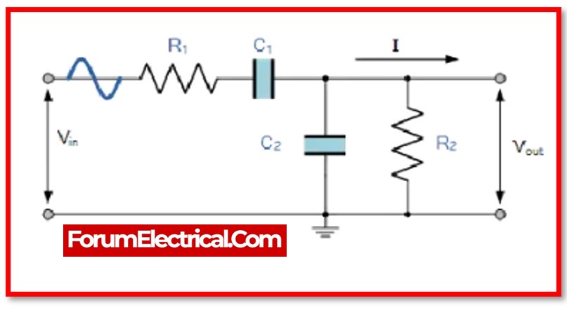
The transfer function of a second-order band pass filter is shown and derived below.
Z1=R1 + (1/jωC1)
Z2=R2 || (1/jωC2)
Z2= {(R2)(1/jωC2)/(R2 + 1/jωC2)}
By Solving the above equations,
ω1=1/T1, ω2=1/T2, ω3=1/T3
Where,
T1=R1C1, T2=R2C2, T3=R3C3
In order to have a band pass filter, the following conditions need to be accomplished:
ω1, ω2 >ω3
Band Pass Filter Cut-off Frequency
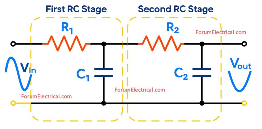
The band pass filter is made up of two filters. As a result, it has two cut-off frequencies. The high pass filter produces one cutoff frequency, which is indicated as Fc-high. The filter accepts signals with frequencies greater than Fc-high. The formula below is used to calculate the value of Fc-high.
Fchigh=1 /2π R2C2
The second cutoff frequency is Fc-low, which is obtained from the low pass filter. The filter accepts signals with frequencies lower than the Fc-low. The formula below is used to calculate the value of Fc-low.
Fclow=1 /2π R₁C₁
The filter operates between Fc-high and Fc-low frequencies. The bandwidth is the distance between these frequencies. As a result, the bandwidth is explained as the following equation.

Bandwidth = Fchigh – Fclow
A high pass filter’s cutoff frequency defines the lower value of bandwidth, while a low pass filter’s cutoff frequency defines the higher (greater) value of bandwidth.
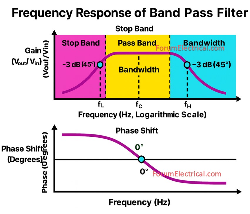
Band Pass Filter – Bode Plot (or) Frequency Response
The frequency response and phase plot of a band pass filter or the bode plot is the signal with a frequency between the bandwidth will be allowed by the filter.
Signals with frequencies lower than the cut-off frequency of the high pass filter will be attenuated by the filter.
And until the signal reaches fl, the output rises at the same rate as the high pass filter: +20 dB.
The output then continues to operate at maximum gain until it reaches the point fh or the cutoff frequency of the low pass filter.
The output will thereafter degrade at the low pass filter’s rate of -20 dB.
Due to the two reactive components in the circuit layout, the band pass filter is a second-order filter. The phase difference, which is 180˚, is therefore twice that of the first-order filter.
The output signal lags behind the input by 90° up to the centre frequency. The output and input signals coincide at the centre frequency. The phase difference is therefore 0˚.
The output signal is 90˚ behind the input signal after the centre frequency.
The Ideal Band Pass Filter
The ideal band pass filter permits signals that are identical to fland have a step response.
The signal allows for a slope of 0 dB at fl precisely. Moreover, it rapidly attenuates transmissions with frequencies higher than fh.
An actual band pass filter cannot be produced by this kind of response.
Equation for a Band Pass Filter
If the frequency of the signal falls within the bandwidth of the filter, then the signal will be allowed through with the input impedance.
When the signal frequency is outside of the bandwidth, the output is 0.
For band pass filter:
P(ω)= 1, ωclow<ω<ωchigh
P(ω)= 0, for other frequencies
Advantages of a Band Pass Filter
- It has a narrow to wide passband and stinging selectivity.
- BPF combines stability and dependability.
- Because of its low cost and small size, it is suitable for a wide range of applications.
- The bandpass filtering approach also improves the receiver’s SNR and sensitivity.
Disadvantages of a Band Pass filter
- Power is required for Active Filters.
- Extremely sensitive to changes in circuit components.
- They have an insertion loss that is inherent to them.
Applications of Band Pass Filters
- The use of these filters is extremely widespread across the spectrum of wireless transmitters and receivers.
- Both the signal-to-noise ratio (also known as S/N ratio) and the sensitivity of a receiver can be improved with the help of this filter.
- The bandwidth of the output signal must be kept within the band that has been chosen for the transmission, and the filter in the transmitter is there to accomplish this task.
- BPFs find widespread application in the field of optics, particularly in devices like LIDARS, lasers, and others.
- This filter is most useful for its application in the processing of audio signals, specifically in situations where it is important to remove all but a certain range of audible frequencies.
- Sonar, instrumentation, medicine, and seismology are just few of the fields that could benefit from these filters.
- These filters utilise communication networks to choose a single signal from among a number of available signals.