
- What is an electrical wiring diagram?
- How to Read an Electrical Wiring Diagram?
- 1). Electrical Schematics (Direction Specification)
- 2). Electrical knowledge (Electrical Understanding)
- 3). The correlations to real circuit components
- 4). The Circuit functions
- 5). Understanding SI units
- 6). The Concept of Polarity
- 7). Connecting the wires together
- 8). Marshalling Ports and Terminals
- 9). Sizes of the cables and information about the wiring
- 10). Dashed Lines (Indicating Connection)
- 11). Wire Tag (Device Tag)
- 12). Understanding Names and Values
- Best Electrical Wiring Drawing Software
What is an electrical wiring diagram?
A wiring diagram is a graphical representation of the components and cables that make up an electrical connection.
The fundamental connections that make an electrical circuit or system significantly more understandable.
A single wiring diagram can represent all of the interconnections, indicating their relative locations.
The use of a wiring diagram is clearly visible in manufacturing or electrical troubleshooting operations. It can prevent a lot of damage and even derail an electrical scheme.
How to Read an Electrical Wiring Diagram?
Many electrical devices include diagrams. The diagrams make it simpler to understand and interpret the quantities in a circuit.
A technician should be able to read these schematics with knowledge and understanding. Reading electrical circuit diagrams might be difficult, but here are some significant features to know.
1). Electrical Schematics (Direction Specification)
Electrical schematics (diagrams) are read from left to right or top to bottom.
It is important to get right since the signal direction reflects the flow of current in the circuit. It is then simple for the user to understand when the circuit’s path changes.
2). Electrical knowledge (Electrical Understanding)
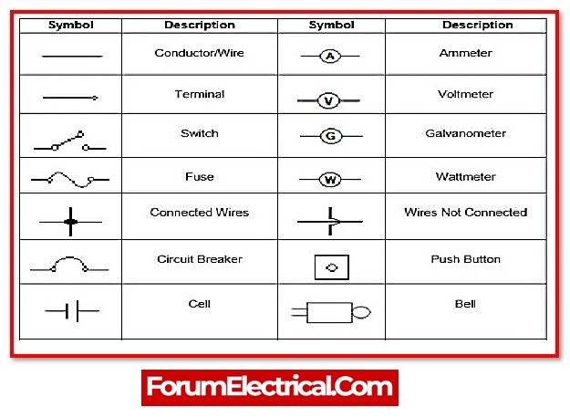
There are several types of schematic symbols that can be used to represent real devices or wires in a circuit.
The ability to understand and read electrical schematics is essential, as incorrect understanding of these elements results in incorrect interpretation.
TO KNOW MORE ABOUT ELECTRICAL SYMBOL
- Straight lines are wires that connect various peripherals in a circuit. This can include light bulbs, switches, and so on.
- A triangle denotes the area of operation for a circuit and represents ground or service.
- Resistors are represented by a zigzag graphic. They protect a circuit against excessive current flow. Resistance is determined by the current scale value.
- Capacitors are depicted in electrical diagrams as parallel lines connected to the main circuit. Capacitors are used to drain sound and fast changes in signal to ground.
3). The correlations to real circuit components
Refer to the user manual to learn about the exact values of the capacitors and resistors.

It is also a good idea to read the manual’s instructions for any electrical device. It will help to determine the specific capabilities of any functioning device.
4). The Circuit functions
Ohm’s Law is used in electrical and electronic engineering to determine values such as resistance, current, and voltage.
The electromotive force (the flow of electrons in the closed circuit) is defined as current, and the formula for calculating current, voltage, and resistance is V=IR.
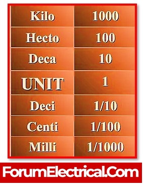
5). Understanding SI units
Every technical field has a standard chart for SI units, which are internationally recognised.
However, many technicians are unaware of the significance of the units. Every electrical professional is required to understand how to read a chart.
It helps in recognizing the unit of each electrical quantity.
SI units are used to quantify electrical quantities. As a result, each unit is unique to a single quantity.
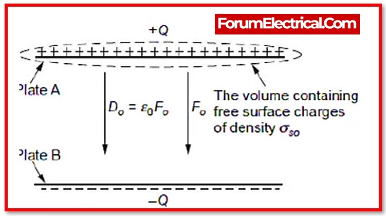
6). The Concept of Polarity
Polarity exists in some circuits. They have both a positive and a negative charge. Understanding polarity is essential.
The law of ‘like charges repel’ and ‘unlike charges attract’ should always be followed. As a result, negative to positive and vice versa.
Most symbols contain polarity indications, making it simple to identify either terminal.
7). Connecting the wires together
In the wiring papers, these wires are linked together by numbers that correspond to the location of the wiring’s intake and outtake.
8). Marshalling Ports and Terminals
Marshalling terminals are used to establish a connection between the panel and the outside field.
Each grouping of the terminals is denoted by the characters (X1, X2, X3,……), and each block of terminals could have from around ten to seventy terminals in total.
9). Sizes of the cables and information about the wiring

When determining the size of a wire for use in electrical installations, it is important to select the appropriate wire size.
The use of a wire that is not adequately sized for the larger loads and higher currents being carried by those loads can cause disruption, which can then lead to the breakdown of the electrical equipment, which can result in dangerous fires and serious casualties.
10). Dashed Lines (Indicating Connection)
There is no diagram that actually works unless there is a key diagram that shows what each symbol represents.
A solid line shows a wire in many electrical diagrams, whereas a dashed line implies functional control, such as a switch or relay coil controlling contacts.
11). Wire Tag (Device Tag)
12). Understanding Names and Values
Values help in defining what a component is. The value of an electrical component, such as a resistor, capacitor, or inductor, informs us how many ohms, farads, or Henries it has.
For other components, such as integrated circuits, the value could represent the chip’s name. Crystals may list the frequency of their oscillation as their value.
The value of a schematic component highlights its most important feature.
| NAME | COMPONENT NAME |
|---|---|
| R | Resistor |
| L | Inductor |
| C | Capacitor |
| D | Diode |
| Q | Transistor |
| S | Switch |
| Y | Oscillator |
| U | Integrated Circuits |
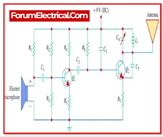
Component names are often made up of one or two letters and a number.
The letter in the name symbolises the component type – R’s for resistors, C’s for capacitors, U’s for integrated circuits, and so on.
Each component name in an electrical drawing should be unique; for example, if there are many resistors in a circuit, they should be labelled R1, R2, R3, and so on.
The names of components allow us to refer to specific points in schematics. Name prefixes are quite highly standardised.
For some components, such as resistors, the prefix is just the component’s first letter. Other name prefixes are not as literal; for example, inductors are L’s (because the current has already taken I).
Best Electrical Wiring Drawing Software
Creating electrical wiring schematics here are some drawing programmes that may be useful to one:
- Electrical AutoCAD
- Smart Draw
- ETAP
- Electric Plan – EPLAN Electric