 control and wiring with detailed diagrams, power connections, control circuits, parameters and safety tips for efficient motor operation.)
 Control and Wiring")
What is a VFD?
A Variable Frequency Drive (VFD) is an electronic device that is used to control the speed and torque of an AC motor by varying:
- Frequency (Hz)
- Voltage (V)
Commonly used in:
- Pumps
- Fans
- Compressors
- Conveyors
A Variable Frequency Drive (VFD) is a powerhouse in industrial automation that is used to control the speed and torque of AC motors by varying the frequency and voltage of the power supplied.
Below is a comprehensive post that is covering the basic connection, wiring and control logic of a VFD system.
VFD Working Principle
A VFD converts fixed frequency AC power into a variable frequency output through 3 primary steps:
Rectifier
Rectifier is used to converts incoming AC (50/60 Hz) into DC.
DC Bus (Capacitor Bank)
DC Bus (Capacitor Bank) filters and smooths the DC voltage.
Inverter
Inverter uses PWM (Pulse Width Modulation) via IGBTs to convert DC back into AC at the desired frequency.
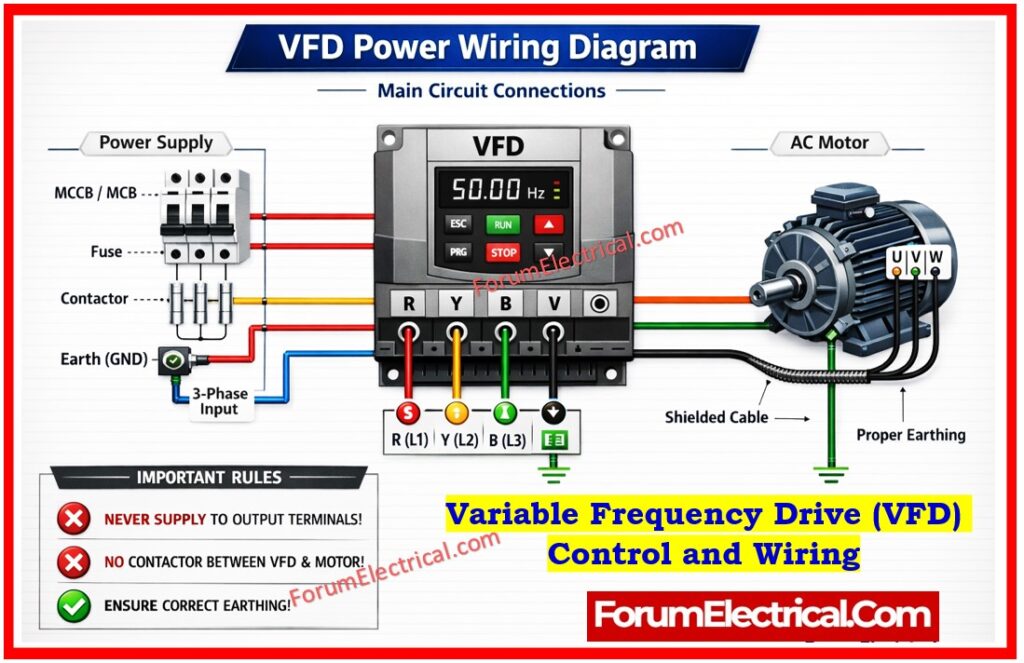
VFD Power Wiring (Main Circuit)
Power wiring involves high voltage (HV) connections. Accurate and safety are critical here to avoid EMI (Electromagnetic Interference).
| Terminal | Description | Details |
|---|---|---|
| L1, L2, L3 | Main Power Input | 3-Phase AC Supply (Line In). |
| U, V, W | VFD Output | Connects directly to the Motor terminals. |
| (+) / (-) | DC Bus Terminals | Used for external braking units or common DC bus setups. |
| PE / G | Ground/Earth | Must be bonded to the panel and motor frame. |
Always use shielded VFD cable for the electric motor connections to avoid electrical noise from disrupting nearby sensors (or) PLC signals.
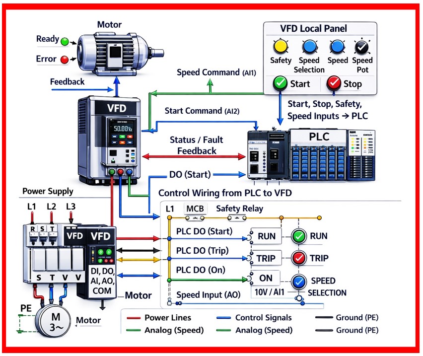
VFD Control Wiring (Control Circuit)
Control wiring can handles the logic, starting/stopping and speed referencing.
These are typically low-voltage (24V DC or 0-10V AC).
A). Digital Inputs (Start/Stop)
Forward/Run (DI1): Closes the circuit to start the motor in the forward direction.
Reverse (DI2): Runs the motor in reverse.
External Fault/Reset: Used to clear trips (or) integrate an E-Stop.
B). Analog Inputs (Speed Reference)
Potentiometer (0-10V): A manual dial to adjust frequency.
PLC Signal (4-20mA): Automated speed control. 4-20mA is preferred over voltage for long distances due to better noise immunity.
C). Output Signals
Relay Outputs: Usually configured to signal “Drive Ready” / “Fault.”
Analog Outputs: To send the actual motor speed (or) current back to an HMI/PLC.
| Terminal | Function |
|---|---|
| DI (Digital Input) | Start/Stop, Forward/Reverse |
| AI (Analog Input) | Speed control (0–10V / 4–20mA) |
| AO (Analog Output) | Feedback signal |
| DO (Digital Output) | Status indication |
| COM | Common terminal |
VFD Control Modes
| Mode | Description |
|---|---|
| Local Mode | Control via keypad |
| Remote Mode | Control via terminals |
| PLC Mode | Automated via PLC |
Important Parameters Setting
Motor Nameplate Data: Rated Voltage, Amps, RPM and Power Factor.
Acceleration/Deceleration Time: How fast the motor used to reaches top speed (e.g., 5.0s).
Minimum/Maximum Frequency: Usually set between 0 Hz and 60 Hz.
Control Source: Command via Terminals (External), Keypad (or) Communication (Modbus/Profinet).
Stop Mode: Ramp-to-stop (controlled) (or) Coast-to-stop (gravity/friction).
| Parameter | Typical Setting |
|---|---|
| Motor Rated Voltage | As per nameplate |
| Motor Rated Current | Nameplate value |
| Base Frequency | 50 Hz |
| Acceleration Time | 5-10 sec |
| Deceleration Time | 5-10 sec |
| Max Frequency | 50/60 Hz |
Control Methods
VFD decides to run the motor depends on the application requirements:
1). V/f Control (Volts per Hertz)
V/f Control (Volts per Hertz) is a simplest method. It keeps the ratio of voltage to frequency constant. Ideal for fans and pumps.
2). Sensorless Vector Control
Sensorless Vector Control is used to calculates motor flux and torque for much tighter speed control without needing an encoder.
3). Closed-Loop Vector Control
Closed Loop Vector Control uses an Encoder feedback. It is essential for cranes, elevators (or) applications requiring full torque at zero speed.
Comparison
| Feature | V/f Control | Sensorless Vector | Closed-Loop Vector |
|---|---|---|---|
| Feedback Required | None | None | Encoder / Resolver |
| Speed Accuracy | 2% – 3% | 0.5% | 0.01% |
| Starting Torque | Low (at low Hz) | High | Maximum |
| Complexity | Very Low | Moderate (Auto-tune) | High (Wiring + Tuning) |
| Cost | Lowest | Moderate | Highest |
| Multi-motor? | Yes | No | No |
Safety and Protection
Dynamic Braking
Using a braking resistor to dissipate energy when a high inertia load needs to stop quickly.
Line Reactors
Installed at the input to protect the VFD from power surges and reduce harmonics.
Overload Protection
The VFD acts as an electronic thermal overload that is tripping if the motor draws too much current for too long.