 and how it works to adjust motor torque and speed by varying the motor input frequency. Explore the different types of VFDs, such as AC, DC, and Servo drives, and their applications in industrial automation, energy efficiency, & motor control systems.)

- What is meant by Variable Frequency Drive (VFD)?
- Basic requirements to use VFD
- What is the function of the variable frequency drive?
- How does a VFD work?
- Why should a VFD be used?
- Speed Torque Characteristics of Induction Motors using Variable Frequency Drive
- Characteristics of VFD
- Advantages of VFD
- Disadvantages of VFD
- Applications of VFD
- Types of VFD
- VFD Implementation Application
- Is a VFD AC or DC?
The term “variable frequency drive” refers to a category of motor controllers that can be used in a wide variety of applications, ranging from home electronics to industrial compressors and more
The variable frequency drive, or VFD, is primarily used to drive and control the speed and torque of the motor so that it can adhere to the needs of the application. This is accomplished by adjusting the supply voltage and frequency.
What is meant by Variable Frequency Drive (VFD)?
A variable frequency drive (VFD) is a motor controller that controls an electric motor by altering the frequency and voltage supplied to the motor. A variable speed drive is also known as an adjustable speed drive, an adjustable frequency drive, an AC drive, a micro-drive, and an inverter.
Frequency (or hertz) is proportional to motor speed (RPMs). In other words, the higher the frequency, the greater the speed of the RPMs. If an electric motor is not required to run at maximum speed in an application, the VFD can be utilised to ramp down the frequency and voltage to match the load requirements of the electric motor. As the motor speed needs of the application change, the VFD can easily increase or decrease the motor speed to fulfil the speed demand.
Basic requirements to use VFD
There are various reasons to utilise a VFD to control motor speed.
- Conserve energy and boost system efficiency.
- In hybridization applications, convert power.
- Match the drive speed to the process requirements.
- Match a drive’s torque (or) power to the process requirements.
- Improve the workplace environment.
- Reduced noise levels ex: fans and pumps.
- Reduce mechanical stress on machinery to help them last longer.
- Minimize peak usage to avoid peak-demand costs and reduce the required motor size.
What is the function of the variable frequency drive?
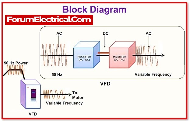
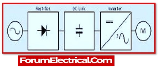
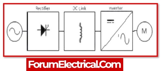
Any Variable Frequency Drive (VFD) comprises the three stages listed below to control a three-phase induction motor.
Below shown is the Variable Frequency drive circuit
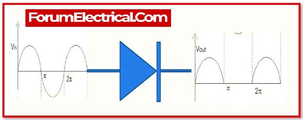
1). Rectifier Stage
A full-wave power diode-based solid-state rectifier converts three-phase 50 Hz electricity from a conventional 220, 440, or higher utility supply to either fixed or adjustable DC voltage. For high voltage systems, transformers may be used.
2). Inverter Stage
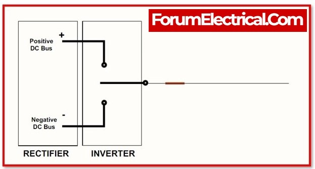
Power electronic switches like IGBT, GTO, (or) SCR switch the DC power from the rectifier on & off to produce a current (or) voltage waveform at the required new frequency. Most voltage source inverters (VSI) typically use pulse width modulation (PWM) because the current and voltage waveform at output in this method is approximately a sine wave. Power Electronic switches, such as IGBTs and GTOs, switch DC voltage at rapid speeds, producing a series of short width pulses with constant amplitude. The gain of the inverter is used to control the output voltage. The output frequency can be changed by adjusting the number of pulses each half cycle or by varying the period for each time cycle.
The resulting current in an induction motor simulates a sine wave with the required output frequency. A PWM inverter’s high-speed switching action results in less waveform distortion and, as a result, lower harmonic losses.
3). Control System
Its function is to control the output voltage, i.e., the voltage vector of the inverter being fed to the motor, and to maintain a consistent voltage-to-frequency (V/Hz) ratio. It comprises of an electrical circuit that receives feedback from the driving motor and changes the output voltage or frequency to the required values. The control system could be based on SPWM (Sine Wave PWM), SVPWM (Space Vector modulated PWM), or any soft computing algorithm.
How does a VFD work?
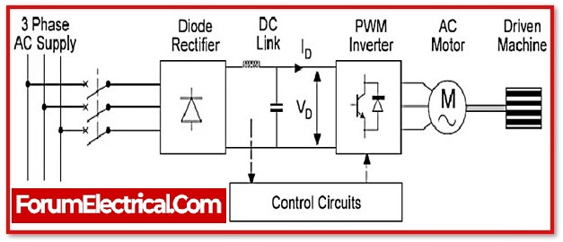
VFDs, both three phase and single phase, can convert input power to a variable frequency and voltage source for controlling the speed of AC induction motors. Based on the equation: the frequency of the power provided to an AC motor determines the speed of the motor.
N = 120 x ƒ / p
where,
N symbolizes for speed (rpm).
f symbolises for frequency (Hz).
p symbolises for the number of motor poles.
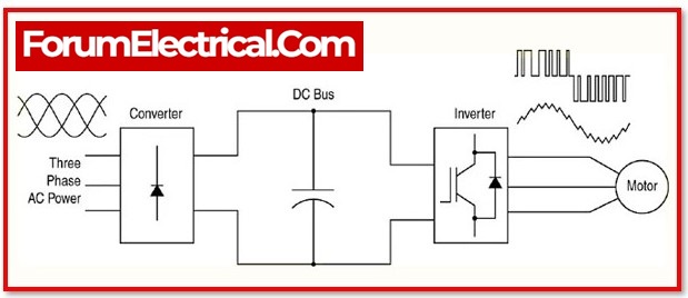
The facility power network provides the AC supply, while the rectifier converts network AC power to DC power. The filter and DC bus collaborate to smooth the rectified DC power and supply clean, low-ripple DC power to the inverter.
The latter inverts an output that simulates sine wave AC power using a pulse width modulation (PWM) technology that switches the inverter semiconductors in variable widths and periods that, when averaged, create a sine waveform.
Why should a VFD be used?
1). Reduce energy consumption and costs
If application does not require full speed, it can save energy by controlling the motor using a variable frequency drive, which is one of the benefits of Variable Frequency Drives. VFDs enable to adjust the speed of motor-driven equipment to the load. There is no other method of controlling an AC electric motor.
Electric motor systems account for more than 65% of industrial power usage today. Motor control system optimization, such as installing or upgrading to VFDs, can reduce energy consumption in operation by up to 70%. Furthermore, the use of VFDs increases product quality while decreasing production costs. When energy saving tax credits and utility rebates are combined, the return on investment for VFD installations can be as low as 6 months.
2). Increase Production by Improving Process Control
By running motors at the most efficient speed for the application, it will make fewer mistakes and so enhance production levels, earning the organisation more income. It eliminates disturbances on conveyors and belts, allowing for high throughput.
3). Increase Equipment Life and Lower Maintenance
When the equipment is controlled by VFDs, which provide appropriate motor application speed, it will last longer and have less downtime due to maintenance. Because of the VFD’s excellent regulation of the motor’s frequency and voltage, it will safeguard the motor from issues such as electro thermal overloads, phase protection, undervoltage, overvoltage, and so on. When start a load with a VFD, the motor or driven load is not subjected to the “immediate shock” of across-the-line starting, but can start slowly, reducing belt, gear, and bearing wear. Because it may have smooth acceleration and deceleration cycles, it is also an effective approach to lessen and/or remove water hammer.
4). Increased Power Factor
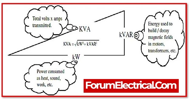
Active power is defined as power converted to rotation, heat, sound, and so on and it is measured in kilowatts (kW). Reactive power is the power that charges magnetic fields or capacitors and is measured in kVAR. The Apparent Power is measured in KVA as the vector sum of the kW and the kVAR. The power factor is the kW/KVA ratio. Full load power factors for typical AC motors can range from 0.7 to 0.8. The power factor decreases as the motor load decreases. The advantage of using VFDs is that they include capacitors in the DC Bus, which maintains a high-power factor on the Variable Frequency Drive’s line side. This avoids the need for additional external and expensive capacitor banks.
5). Recovery of Slip Power
The fundamental power supplied to the rotor by the stator is known as air gap power Pg. The mechanical power generated is provided by
Pm= Pg-sPg
Where,
sP -Slip Power
Pm – Mechanical Power and
Pg– Air Gap Power
a). Scheme for Slip Power Recovery
If the slip is particularly large, i.e., the speed is low, there is a lot of power consumed.
Ex: kiln drives in the cement industry.
This power can be conserved by implementing a slip recovery method. Slip power is first acquired in this system using WRIM brushes. This recovered slip power is then rectified and inverted back to line frequency before being fed into the supply via a coupling transformer.
Speed Torque Characteristics of Induction Motors using Variable Frequency Drive
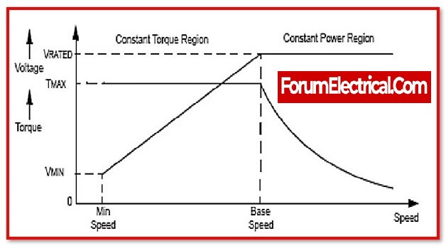
In a stator-induced induction motor, E is proportional to the product of the air gap flux and the slip frequency. If stator drop is neglected, the terminal voltage is proportional to the product of the slip frequency and flux. Any reduction in supply frequency without a corresponding change in terminal voltage will increase the air gap flux, resulting in magnetic saturation of the motor. Also, the motor’s torque capacity is decreased. Therefore, when driving a motor with a VFD or Variable Frequency Drive, it always maintain a consistent V/f ratio.
Variable K described in the following:
K = f/frated
- For operating below K <1, i.e., below the rated frequency, constant flux operation is used. For this, keep the magnetization current Imconstant at all operational points.
- For K > 1, i.e., above the rated frequency, maintain the rated terminal voltage V. This field is weakened by the inverse ratio of frequency per unit ‘K’.
- For values of K = 1, torque is constant, while power is constant for values greater than 1.
Characteristics of VFD
1). Line Voltage
It is important to specify the operating voltage of a variable frequency drive. This measurement is typically 240 (or) 480 volts AC. The measurement can accept a 10% variance in voltage.
Whenever recording a voltage reading for a significant application, it is essential to consider for power variations.
2). Continuous Operating Current Rating
This is the maximum root-mean-square (rms) current that a VFD can safely take under all working conditions and a constant ambient temperature usually 400C.
This rating is significant because it must be equal to or greater than the sine wave currents of the motor ball load in order for an electric motor to operate properly.
3). Overload Current Rating
This is the maximum amount of current that a VFD can generate over a particular period of time. It is expressed as an inverse current/time rating.
Advantages of VFD
1). Improved Efficiency
When compared to the variable frequency method, conventional speed control employing the variable voltage method consumes a lot of energy. As a result, VFDs are utilised in industries to boost motor efficiency and save a significant amount of energy.
2). Precise Control
A VFD provides for tighter control of speed with the use of a sensor to run the motor at an effective speed that does not cause obstruction and boosts production speed in industries.
3). Limits Inrush Current
Inrush current refers to the huge initial current produced by an induction motor during start-up. Its rated current is 5 to 8 times higher. It has the potential to harm the motor’s windings. The VFD can safely limit starting current and is utilised in one of the methods for starting induction motors.
4). Increase Mechanical Life
It can start and stop a motor safely with a gradual shift in speed and no mechanical jerks. It increases the motor’s mechanical life.
5). Reduced Maintenance
Smooth motor running decreases mechanical stress and eliminates jerks, reducing the maintenance required for such motor. As a result, the long-term cost is reduced.
6). Power Factor
A low power factor results in reactive power loss, which is energy squandered as heat. The power factor of an induction motor is often low. A VFD increases the power factor, allowing for more efficient power utilisation.
7). Protection
A VFD can also provide overload, overvoltage, and phase loss protection. In the event of such a problem, it promptly cuts off the supply current to protect the associated load from damage.
8). Simple Installation
They are easier to instal and operate since they are pre-programmed with an easy-to-use and friendly user interface during production.
Disadvantages of VFD
1). Initial Cost
VFDs cost more than direct on-line or across-the-line motor starters. As a result, the initial cost of installing VFDs in a large production is rather significant.
2). Design of a Special Motor
The VFD’s PWM-based AC output is not a pure sinusoid. It can cause stress in the windings of a standard AC motor, causing it to heat up and destroy the winding insulation. To run with a VFD, a specific motor with enhanced insulating design certified for PWM inverter is necessary.
3). Harmonics
The VFD can generate harmonics in the power supply. The rectifier circuit’s non-linear current draw causes supply distortion, which affects the electrical equipment connected in parallel. As a result, additional harmonic filters are required.
4). Operation Complication
5). Extreme Circumstances
Of comparison to a DOL starter, the electronic circuitry in a VFD is more sensitive, and its operation is influenced by extreme cold or heat. To respond with such a harsh environment, additional precautions are required.
Applications of VFD
- The variable-frequency function is used to alter the speed of an induction motor, the speed of which is completely determined by frequency.
- It is used in conveyor belt systems for precise motor speed control with smooth starting and stopping to reduce accidents and boost production.
- Temperature is also maintained via accurate speed control in the cooling system.
- The smooth start and stop feature of VFD is used in lifts and escalators.
- They are used in water pumps as well as mining crushers.
- VFDs are used in hoists and cranes to precisely control speed and positioning.
Types of VFD
VFDs are divided into three types based on the mode of power conversion.
1). Voltage Source Inverter type VFD (VSI VFD),
2). Current Source Inverter type VFD (CSI VFD) and
3). Pulse Width Modulation VFD (PWM VFD)
1). Voltage Source Inverter type VFD (VSI VFD)
The most popular type of VFD is the VSI, or Voltage Source Inverter. It generates a smooth voltage waveform that is proportional to the output frequency. It features a simple design that includes a diode rectifier and a capacitor for filtering and storing DC energy. An inverter is then used to convert the DC voltage to AC voltage. They have a high operating speed and can regulate several motors.
The major drawback of VSI is that they have poor power factors and induce motor cogging at low frequencies below 6 Hz. They are also non-regenerative, which implies they cannot store the energy that flows back from the motor.
Advantages of VSI VFD
- It has a relatively simple design.
- It is significantly not expensive and more cost-effective.
- It has widely operating speed range.
- It possesses the ability to control several motors.
Disadvantages of VSI VFD
- It has an extremely low power factor, particularly at low speeds.
- It causes the motor to cog at frequencies lower than 6Hz.
- The cogging causes the motor to jerk as it starts and stops.
- At its output, various harmonics are generated.
- They do not regenerate.
2). Current Source Inverter type VFD (CSI VFD)
In comparison to the smooth voltage waveform of the VSI type, the CSI or Current Source Inverter type VFD gives a smooth current waveform. It stores and delivers constant DC current using huge and costly inductors.
It consists of SCR-based rectifiers for converting AC to DC and a series of inductors for filtering and storing the DC current. The inverter transforms direct current (DC) to alternating current (AC).
The CSI-type VFDs feature regenerative power capabilities, which indicates they can store energy that is returned from a load, such as a motor. However, they also generate motor cogging at low frequencies less than 6Hz. They are mostly employed in signal processing.
Advantages of CSI VFD
- It has regenerative characteristics, which allow it to absorb the power returned by the motor.
- It acts as a steady current source for high-power motors.
- It has a relatively simple design.
- It is more reliable than the VSI VFDs.
Disadvantages of CSI VFD
- It has a low power factor, particularly at low speeds.
- The inductors are large and expensive.
- Overall, the CSI VFD is more expensive than the VSI VFD.
- It causes cogging and jerks in the motor shaft when starting and stopping.
- It cannot run many motors at the same time, unlike the VSI type.
3). Pulse Width Modulation VFD (PWM VFD)
PWM, or Pulse Width Modulation, is a technique for varying the average power produced by varying the duty cycle of a signal. PWM-based VFDs simulate a sinusoidal waveform by using fixed DC voltage pulses with varying duty cycles. Because it is an enhanced form of VSI, it delivers stable voltage with a higher power factor.
It has a simple diode bridge rectifier that converts alternating current to direct current. The Control Unit is set up to control the duty cycle of the inverted output by regulating the inverter’s switching speed. It also requires the addition of an additional regulator at its output to regulate the voltage pulses and give a smooth voltage and current waveform.
Because of its significant advantages over the VSI and CSI VFDs, it is the most commonly utilised approach in VFDs. For example, it does not induce cogging in the motor, resulting in increased efficiency. It features an improved power factor. However, they are difficult to develop and implement. They also necessitate a separate circuit for voltage and current regulation.
Advantages of PWM VFD
- It has a higher power factor.
- It does not cause motor cogging.
- It is far more efficient than VSI and CSI.
Disadvantages of PWM VFD
- Its design and implementation are complex.
- It requires the use of an additional hardware circuit, the regulator.
- It expensive more than VSI and CSI.
VFD Implementation Application
VFD can also be implemented by the microcontroller circuit which is given below.
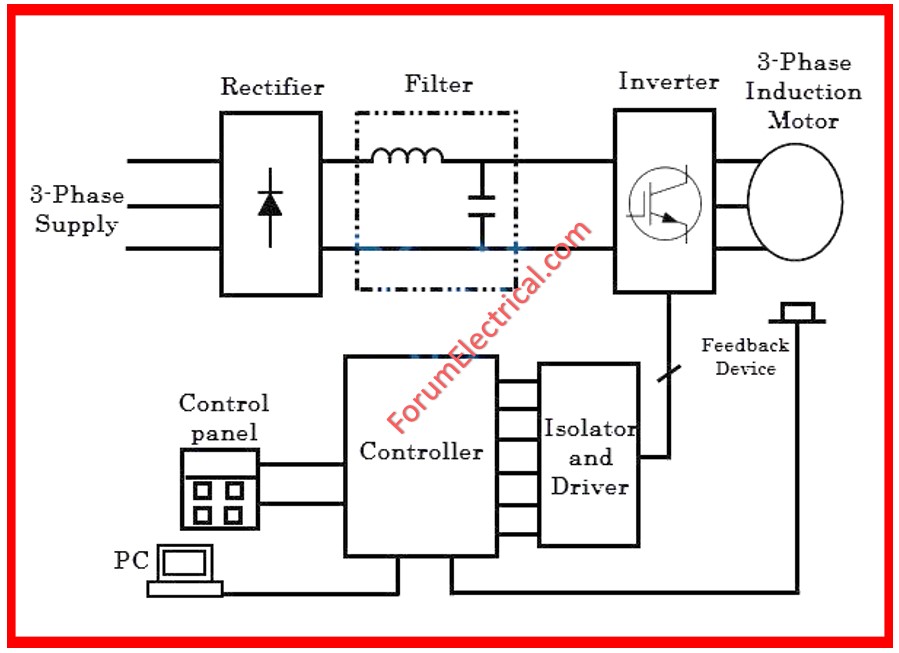
It is similar to VFD, which is comprises rectifier section, filtering, and then an inverter section.
Here inverter section receives the firing pulses from the above programmed micro controller to give variable voltage and frequency to the load.
This project is known as single phase to three phase converter by using Space Vector Pulse Width Modulation technique to control the AC voltage and frequency over the load.
Is a VFD AC or DC?
A variable frequency drive (VFD) relates only to AC drives, but a variable speed drive (VSD) can be either AC or DC.
VFDs control the speed of an alternating current motor by altering its frequency.
VSDs which refer to DC motors, adjust the speed by altering the voltage applied to the motor.