 Testing, its working principle, causes, detection methods and importance in transformers, GIS, cables, motors and HV equipment to detect insulation failure before breakdown.)
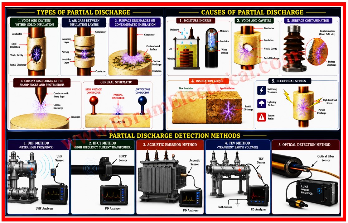
Partial Discharge (PD) testing has developed as one of the most advanced diagnostic testing techniques in the condition monitoring of high voltage electrical equipment.
- What is Partial Discharge?
- How Partial Discharge occurs?
- Inception Voltage
- Importance of PD Testing
- Equipment & Applications
- Causes of Partial Discharge
- PD Deterioration Progression
- Partial Discharge Detection Methods
- UHF Method (Ultra High Frequency)
- HFCT Method (High Frequency Current Transformer)
- Acoustic Emission Method
- TEV Method (Transient Earth Voltage)
- Optical Detection Method
- Testing Procedures & Precautions
- Pre-Testing Checklist
- Essential Precautions
- Testing Voltage Application
- Interpretation & Analysis
- Conclusion
The ability to detect faults through PD testing allows maintenance teams to adopt condition based maintenance strategies, optimizing both maintenance costs & equipment availability.
This post covers the technical aspects, practical applications & best practices for Partial Discharge testing in high voltage equipment.
What is Partial Discharge?
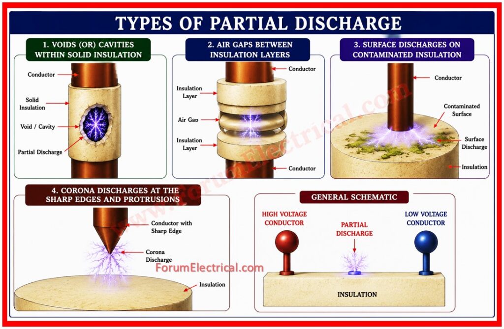
Partial Discharge (PD) is defined as a localized electrical discharge that occurs in an insulating medium without completely bridging the electrodes.
It is an electrical discharge confined to a small portion of the total insulating material between conductors such as:
- Voids (or) cavities within solid insulation.
- Air gaps between the insulation layers.
- Surface discharges on the contaminated insulation.
- Corona discharges at the sharp edges and protrusions.
How Partial Discharge occurs?
When an electrical field stress exceeds the breakdown strength of the localized region (such as within a void) ionization occurs.
This leads to the formation of a small electrical discharge that partially bridges that region without involving any complete insulation. This discharge
- Generates electromagnetic radiation in the UHF (Ultra High Frequency) range,
- Produces acoustic signals (sound waves),
- Creates electrical pulses detectable by the sensitive sensors and
- Generates heat and degrades the insulating material
Inception Voltage
The Partial Discharge Inception Voltage (PDIV) is the minimum voltage at which PD first occurs in a given configuration.
The PD Extinction Voltage (PDEV) is the voltage below which the PD ceases to occur.
These parameters are essential in understanding the voltage stress on equipment & help engineers to predict when PD activity may begin.
Importance of PD Testing
Early Detection of Insulation Defects
Many catastrophic equipment failures that used to start silently via partial discharge (PD) activity without any visible signs.
By detecting partial discharge (PD) in its early stages maintenance teams can intervene before costly breakdowns occur.
Prevention of Major Equipment Failures
Undetected partial discharge progresses through stages of insulation degradation that is eventually leading to complete breakdown.
Early PD detection enables corrective actions such as equipment repair, replacement (or) more frequent monitoring and preventing unplanned outages.
Condition Based Maintenance
By trending PD activity over time, utilities can transition from time-based preventive maintenance to condition based maintenance.
This procedure optimizes the maintenance intervals, reduces unnecessary interventions and extends equipment life.
Enhanced Equipment Reliability
Continuous PD monitoring used to improve the overall reliability of the electrical system.
Equipment that is properly maintained based on its actual condition rather than the assumed method of degradation rates that operates more dependably.
Cost Optimization
While PD testing represents an additional implement in diagnostic capabilities and it saves cost by:
- Avoiding the catastrophic failures that cause extended outages.
- Reducing the emergency replacement costs.
- Optimizing the maintenance resource allocation.
- Extending the equipment life via early intervention.
Equipment & Applications
Power Transformers
Power transformers are the most important in electrical networks and their failure may cause widespread outages.
PD testing in transformers typically focus on:
- Windings: Detecting the insulation degradation and voids.
- Core: Identifying the delamination (or) insulation failures.
- Oil-Paper Interface: Detecting the moisture and contamination.
Gas Insulated Switchgear (GIS)
GIS is used extensively in high-voltage substations.
PD detection in GIS is particularly valuable because the enclosed nature of the equipment makes visual inspection difficult.
Internal defects such as:
- Particles trapped in SF. gas
- Surface defects on insulators
- Moisture contamination in the gas
High Voltage Cables
Submarine cables, underground cables & aerial cables are prone to moisture ingress and mechanical damage.
PD testing helps to identify:
- Water treeing in polymeric cables,
- Voids in insulation layers and
- Termination defects.
Motors and Generators
Large motors and generators in industrial applications need reliable operation.
PD testing detects:
- Winding insulation degradation,
- Turn-to-turn faults developing and
- Stator core insulation weakening.
Bushings and High Voltage Insulators
Bushings are vulnerable to aging and moisture ingress.
PD testing identifies insulation degradation before failures cause the power loss (or) equipment damage.
Causes of Partial Discharge
Moisture Ingress
Water molecules reduce the dielectric strength of insulation.
In transformers, moisture combines with oil to form acids that further degrade insulation.
In cables & GIS moisture creates conductive paths and initiates water treeing.
Voids and Cavities
Manufacturing defects, poor impregnation (or) mechanical stress can create air-filled voids in solid insulation.
These voids have much lower breakdown strength than the surrounding material and readily initiate PD at lower voltages.
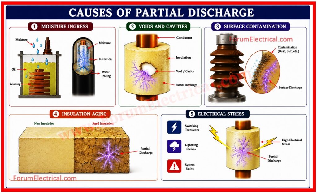
Surface Contamination
Dust, salt and other particulates accumulate on the insulation surfaces forming conductive paths that enable surface leakage currents and surface discharges especially in humid environments.
Insulation Aging
Thermal aging, oxidative degradation and radiation exposure degrade insulation over decades of operation.
Aged insulation becomes brittle & loses its dielectric properties making it susceptible to PD.
Electrical Stress
Overvoltages from
- Switching transients,
- Lightning strikes and
- System faults
increase electrical stress on insulation.
High electrical stress accelerates ionization processes and PD initiation.
PD Deterioration Progression
The progression of PD that induced failure typically follows these stages.
| Stage | Characteristics | Action Required |
|---|---|---|
| Initiation | Partial Discharge (PD) starts at PDIV (Partial Discharge Inception Voltage) with a low activity level and minimal insulation degradation. | Monitor closely and establish a baseline trend for the future comparison. |
| Propagation | PD activity gradually increases and insulation defects expand and the trend becomes more noticeable over time. | Plan corrective action during the next maintenance (or) service window. |
| Acceleration | Rapid increase in PD activity with possible chemical signatures, thermal stress, ozone formation, carbon tracking (or) insulation damage becoming severe. | Urgent action required and consider repair, refurbishment (or) component replacement. |
| Breakdown | PD transitions into a major fault condition that is leading to complete insulation failure (or) imminent flashover/breakdown. | Immediate removal from service and emergency replacement to prevent the catastrophic failure. |
Partial Discharge Detection Methods
UHF Method (Ultra High Frequency)
The UHF method detects electromagnetic radiation generated by partial discharge events in the frequency range of 300 MHz to 3 GHz.
Advantages
- Excellent for GIS and other enclosed equipment.
- Less affected by external electromagnetic noise.
- High frequency allows for localization.
Disadvantages
- Expensive equipment & sensors.
- Requires expertise in signal processing.
HFCT Method (High Frequency Current Transformer)
HFCT detects high frequency current pulses caused by PD events flowing through conductors.
It measures capacitive coupling of PD current to the power conductor.
Advantages
- Non-invasive-clamps around conductors,
- Effective for cables and overhead lines and
- Can be deployed during operation.
Acoustic Emission Method
This method uses sensitive acoustic sensors to detect the sound waves generated by the PD method.
Typical frequencies are 100 kHz to 1 MHz.
Advantages
- Can be used in oil-immersed transformers and
- Allows localization of PD source.
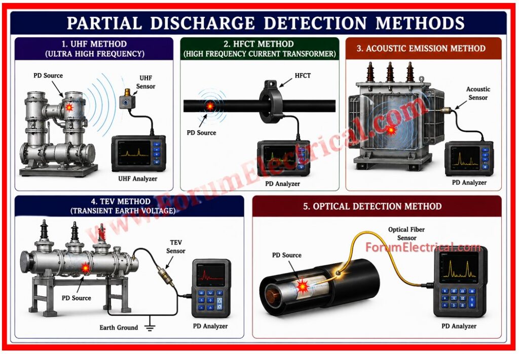
TEV Method (Transient Earth Voltage)
TEV detects the transient voltage pulses that appear between the grounded equipment and earth potential due to PD events in GIS.
Advantages
- Portable and easy to use
- Non-invasive
Optical Detection Method
This emerging technique uses the optical fiber sensors to detect light emission from the PD method.
It is particularly useful for distributed sensing along cables.
International Standards
- IEC 60270
- IEC 61000-4-16
- IEEE C57.97
- CIGRÉ Guides
Testing Procedures & Precautions
Pre-Testing Checklist
- Verify the equipment specifications and voltage rating.
- Ensure a proper grounding and bonding.
- Calibrate all the testing equipment as per ISO 17025.
- Establish baseline measurements and historical data.
- Document the environmental conditions (temperature, humidity).
Essential Precautions
High Voltage Safety: Always follow lockout tagout (LOTO) procedures.
Shielding: Utilize a proper shielding cable & protects to minimize the external noise coupling.
Environmental Stability: Perform the tests under a stable temperature & humidity conditions.
Equipment Calibration: Verify the sensor calibration before & after testing.
Noise Mitigation: Identify & eliminate the external EMI sources during testing.
Data Recording: Maintain a complete detailed record of all measurements & trends.
Testing Voltage Application
Partial discharge (PD) testing typically follows one of 2 protocols:
Step-Voltage Method: Voltage is gradually increased in steps, with PD monitored at each level.
Stabilized Voltage Method: Equipment is subjected to a steady test voltage for a specified time period.
Interpretation & Analysis
Key Performance Indicators
Apparent Charge (qm): Measured in picocoulombs (pC) that represents the total charge transferred.
Repetition Rate (n): Number of partial discharge (PD) pulses/second.
PD Inception Voltage (PDIV): Voltage at which partial discharge (PD) first appears.
PD Extinction Voltage (PDEV): Voltage below which partial discharge (PD) ceases.
Trend Analysis
Trend analysis is the most valuable aspect of partial discharge (PD) monitoring.
The progression of partial discharge (PD) levels over time rather than absolute values which indicates the rate of insulation degradation:
Stable Trend: Partial discharge (PD) levels remain constant-equipment is stable.
Linear Increase: Slow and predictable degradation-plan maintenance.
Exponential Increase: Rapid degradation and urgent attention required.
Phase Resolved PD Patterns
By analyzing partial discharge (PD) patterns relative to the AC voltage waveform engineers can infer the type of defect:
Void Discharge: Bipolar pattern with pulses near both 1/2 cycles.
Surface Discharge: Clustered pulses concentrated in one 1/2 cycle.
Corona Discharge: Continuous pulses with a fine structure.
Conclusion
Partial Discharge testing represents a paradigm shift in high voltage equipment diagnostics.
By detecting the faults before they cascade into catastrophic failures, partial discharge (PD) testing enables utilities and industrial operators to adopt advanced condition based maintenance strategies that optimize costs, enhance reliability & extend equipment life.