
Power factor testing is one of the most important diagnostic methods used to assess the condition of power transformer insulation systems.
- Purpose
- Equipment Required
- Safety Precautions
- Pre-Test Preparation
- Record Nameplate and Ambient Data
- Short All Bushing Terminals
- Connect Ground Lead
- Test Connections for Two-Winding Transformers
- Test Procedure
- Step 1: Prepare Test Set
- Step 2: Connect for Tests 1, 2 and 3
- Step 3: Perform Test 1 (GST, H Winding to Ground)
- Step 4: Perform Test 2 (GST with X Winding Guarded)
- Step 5: Perform Test 3 (UST, Interwinding H-to-X)
- Step 6: Calculate Test 4
- Step 7: Reverse Leads for Tests 5, 6 and 7 (If Required)
- Step 8: Individual Bushing Tests
- Step 9: Restore Connections
- Temperature Correction
- Recording Test Data
- Interpreting Test Results
- Acceptable Power Factor Limits
- Interpreting Changes in Readings
- Bushing Conditions
- Special Transformer Types
- Three-Winding Transformers
- Autotransformers
- Wye-Wye Transformers with Non-Separable Neutrals
- Post-Test Procedure
- Summary
The test measures the dielectric losses in insulating materials, revealing conditions such as
- Moisture ingress,
- Carbonization,
- Contamination and
- General insulation degradation & problems that may not be visible through routine visual inspection alone.
Transformers are an important component in electrical power systems.
Detecting insulation deterioration early through periodic power factor testing enables maintenance teams to schedule corrective action prior to a catastrophic failure that is reducing unplanned outages & costly repairs.
This post outlines the complete step-by-step procedure for conducting the power factor tests on two winding & three winding power transformers.
Purpose
Power factor testing is performed to
- Detects moisture, contamination and carbonization in the transformer windings and liquid insulation.
- Identify the insulation deterioration due to aging, overheating (or) electrical stress.
- Establish baseline measurements for the new transformers and track the changes over time.
- Isolate the location of insulation faults by comparing the measurements across winding combinations.
- Supplement other tests such as excitation current, winding resistance and turns ratio tests.
This procedure applies to
- Two-winding oil-filled power & distribution transformers.
- Three-winding transformers with a tertiary winding.
- Transformers equipped with load tap changers (LTC) (or) no-load tap changers (NLTC)
Equipment Required
Before starting the test procedure ensure the following equipment is available and in calibrated condition.
| Equipment | Description / Notes |
| Power Factor Test Set | Doble M4000, Delta 2000 (or) equivalent. Should be capable of 2.5 kV & 10 kV output. |
| High Voltage Lead | Rated for the test voltage and kept clear of grounded surfaces during testing. |
| Low Voltage Lead | For connection to guarded winding (or) return path. |
| Ground Lead | Connects the test set ground to transformer tank ground. |
| Shorting Wires / Jumpers | Heavy-gauge, insulated and used to short bushing terminals. Should not sag. |
| Thermometer | To record the top oil temperature & ambient temperature. |
| Hygrometer | To record the relative humidity at time of test. |
| Test Record Sheets | Document all nameplate data, readings and observations. |
| Personal Protective Equipment | HV rated gloves, safety glasses, arc flash protection per NFPA 70E. |
Safety Precautions
All safety procedures should be strictly observed. Failure to comply may result in serious injury (or) death.
Warning: Never perform the electrical tests on a transformer that is under vacuum. Flashovers can occur at voltages as low as 250 volts (250 V).
- Ensure the transformer is completely de-energized, isolated & locked out / tagged out (LOTO) in accordance with the organizations safety procedures before start testing.
- Verify that the transformer is properly grounded to the system ground before connecting any test leads.
- Before applying any test voltage, confirm that all the bushing current transformers (BCTs) are shorted out to prevent (avoid) induction of hazardous voltages.
- Remove the neutral ground connection from the transformer winding before testing. Restore after testing is complete.
- If the transformer is equipped with a load tap changer (LTC) then set the tap changer to a position off neutral before testing. Some LTC designs include contactor elements that are not effectively shorted in the neutral position even with the bushings shorted.
- Connect a ground wire from the test set chassis to the transformer ground terminal before connecting to any test leads.
- Ensure all (HV) high voltage test cables extend away from the bushing & are kept clear of grounded structures during testing.
- Inspect the shorting wires to confirm and verify whether they are secure & do not sag which would cause critical accidental contact with the grounded surfaces.
- Wear appropriate PPE including voltage rated rubber gloves and arc flash protection throughout the testing procedure.
Pre-Test Preparation
Record Nameplate and Ambient Data
Complete documentation is important for meaningful comparison of results over time. Before starting the electrical tests record the following:
- Transformer serial number, manufacturer, type/model and KVA/MVA rating.
- Winding voltage ratings (e.g., 138 kV / 13.8 kV), connection (delta / wye) and BIL.
- Nameplate capacitance (C1 & C2) and power factor values if available.
- Load tap changer position at time of test.
- Ambient temperature (dry bulb), top oil temperature and relative humidity.
- General weather conditions (sunny, overcast, humid, raining).
Note: Power factor testing is sensitive to temperature and humidity. Whenever possible conduct tests in dry conditions with ambient temperatures near 200C for most accurate comparison to standard values.
Short All Bushing Terminals
Using heavy-gauge insulated shorting wires, connect and short all terminals of each winding together including the neutral terminal of any wye-connected winding.
The neutral ground should be removed before shorting.
Verify that all shorting connections are tight and that wires do not sag.
Connect Ground Lead
Attach the ground lead from the test set to the dedicated transformer ground point on the tank.
This ensures the test set reference ground is the same as the transformer tank ground throughout all test steps.
Test Connections for Two-Winding Transformers
The following test sequence is utilized for standard two-winding oil-filled transformers.
Tests are performed at 2.5 kV (or) 10 kV.
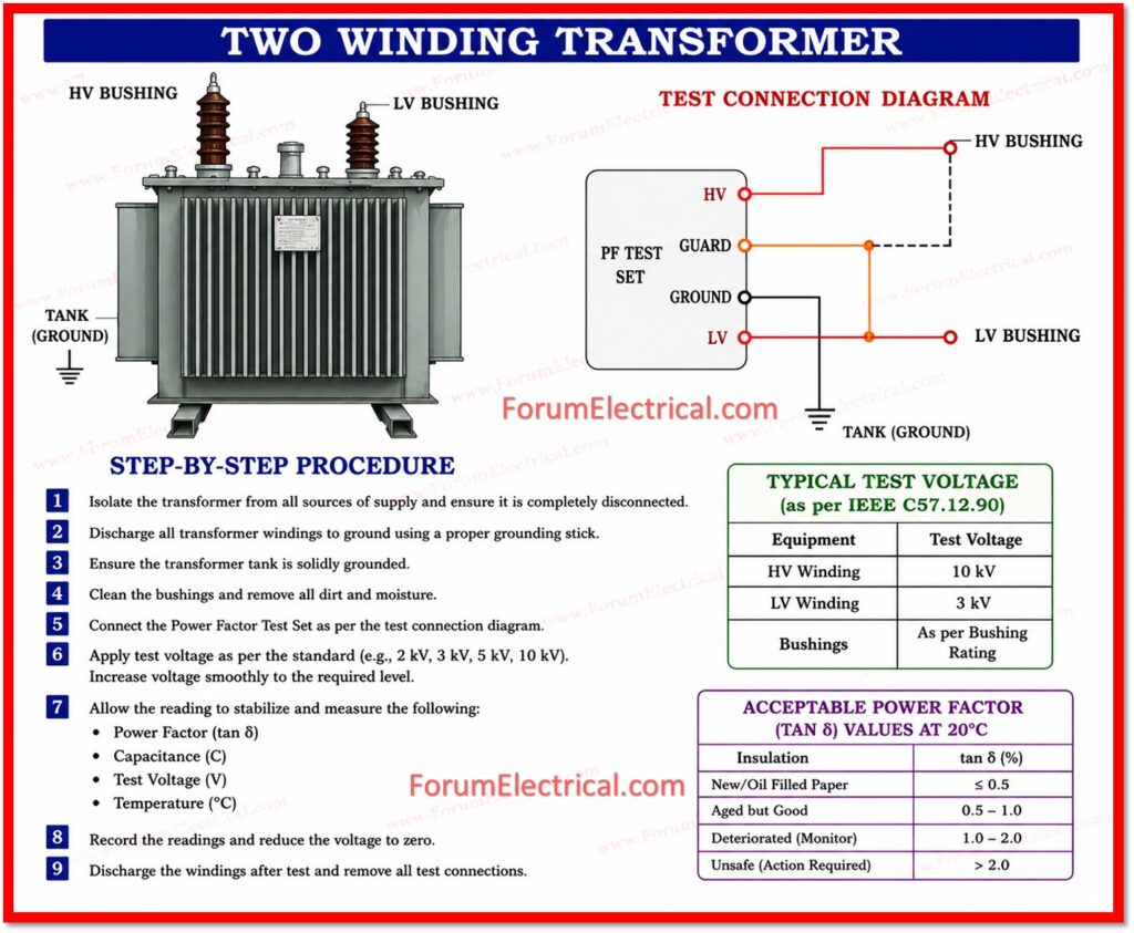
If either voltage exceeds the rated insulation level of the winding under test apply voltage at (or) slightly below the winding rating.
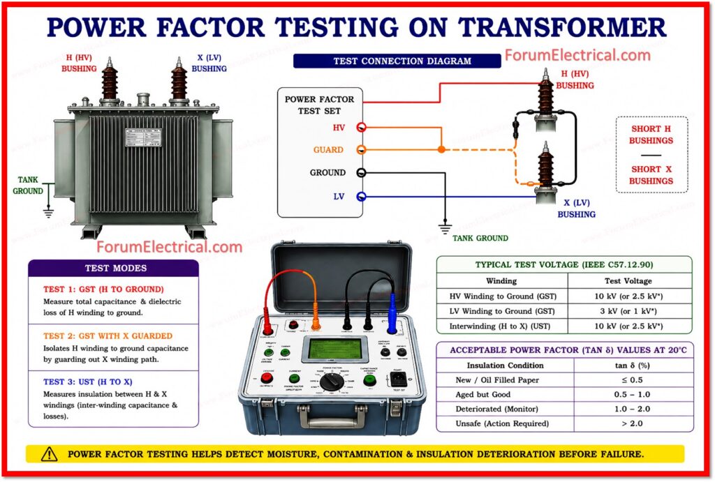
Tests 1, 2 and 3: High Voltage Lead on H Bushings
Connect the high voltage (HV) lead from the test set to the high-voltage (H) bushings.
Connect the low voltage (LV) (ground) lead to the low-voltage (X) bushings.
| Test No. | Mode | HV Lead Connected To | Description |
| Test 1 | GST | H Bushings | CH Winding Capacitance to Ground |
| Test 2 | GST | H Bushings (X Guarded) | CH+X to Ground (guarded) |
| Test 3 | UST | H Bushings | CHL Inter-winding (H-to-X) |
Note: Test 4 is a calculated value: subtract the capacitance & watts of Test 2 from Test 1. The result must match the UST measurement of the CHL insulation (inter winding capacitance).
Tests 5, 6 and 7: Reversed Leads (X Bushings as HV)
Reverse the test leads: connect the high voltage (HV) lead from the test set to the low-voltage (LV) (X) bushings and connect the low voltage (return/ground) lead to the high-voltage (HV) (H) bushings. Apply test voltage that is suitable for the secondary winding rating.
Tests 5, 6 & 7 are not routinely conducted unless the results from Tests 1, 2 & 3 indicate a potential problem or fault. They provide some additional diagnostic data by measuring the insulation (using megger) from the X winding perspective.
Note: Test 8 is a calculated value: subtract Test 6 from Test 5. Results should compare with the UST measurement in Test 7 for the CHL insulation.
Test Procedure
Step 1: Prepare Test Set
Position the power factor (PF) testing set near the transformer.
Verify the test set calibration date is current.
Connect the test set ground lead to the power transformer ground point.
Power on the test set & use to allow it to warm up as per the manufacturers instructions.
Step 2: Connect for Tests 1, 2 and 3
Connect the (HV) lead (i.e., high voltage) to the shorted H bushings.
Connect the (LV) lead (i.e., low voltage) to the shorted X bushings.
Verify all the shorting wires that are secure & that the neutral ground has been removed (or) isolated.
Step 3: Perform Test 1 (GST, H Winding to Ground)
Select Grounded Specimen Test mode (GST Test mode) on the test set.
Apply 10 kV (or 2.5 kV if 10 kV exceeds winding rating).
Record the actual test voltage, current in milliamperes, watts loss, power factor percentage and capacitance in picofarads.
This measures the total capacitance & dielectric loss of the H winding to ground.
Step 4: Perform Test 2 (GST with X Winding Guarded)
Without changing connections switch to the guarded mode (X winding guarded).
Repeat the test & record all values.
This measurement isolates the H winding to ground capacitance path by guarding out the X winding path.
Step 5: Perform Test 3 (UST, Interwinding H-to-X)
Switch the test set to (UST) Ungrounded Specimen Test mode.
Apply the test voltage & record all the values.
This test is used to measure the insulation between the H & X windings (CHL) that is the primary inter-winding barrier.
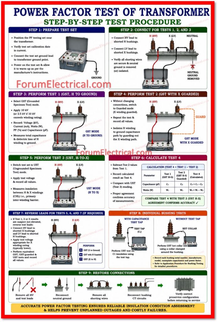
Step 6: Calculate Test 4
Subtract the capacitance & watts values of Test 2 from the Test 1.
Record the calculated result which is obtained as Test 4.
Compare this calculated result which is obtained to the UST reading in Test 3.
Proper & verified agreement confirms the accuracy (exact) of the measurements.
Step 7: Reverse Leads for Tests 5, 6 and 7 (If Required)
If Test 1, 2 (or) 3 results are suspect (or) elevated, reverse the test leads:
Connect the high voltage (HV) lead to the shorted X bushings and the low voltage lead to the shorted H bushings.
Apply test voltage at a level appropriate for the X winding rating (typically lower).
Perform the equivalent GST, GST-guarded & UST tests and record all values.
Step 8: Individual Bushing Tests
With windings remaining shorted perform individual power factor tests on each bushing as
- Bushings equipped with a capacitance test tap: perform UST test on the C1 insulation using the test tap.
- Bushings without a test tap: perform GST hot collar test using a collar clamped around the bushing.
Record each bushing serial number, manufacturer, model, nameplate capacitance and power factor.
Refer to the application procedure for Bushing Testing for detailed procedures.
Step 9: Restore Connections
After all tests are complete remove all high voltage (HV) and test leads.
Reconnect the neutral ground.
Remove all shorting wires.
Reconnect bushing current transformer (CT) circuits.
Verify the transformer is in the correct preservice configuration before returning to service.
Temperature Correction
Power factor values are temperature-dependent and should be corrected to the standard reference temperature of 200C to allow comparison between tests conducted at different times & under different temperature conditions.
- Correct transformer winding power factor readings using the top oil temperature at the time of testing. Use the Temperature Correction Factor chart for Liquids, Transformers & Regulators.
- Correct bushing power factor readings using the ambient temperature. Use the Bushing Temperature Correction Factor chart from the same reference.
- Record both the approximate measured value (approx.) & the corrected value at 200C on the test data sheet.
Recording Test Data
Proper documentation is more essential for trend analysis & for future test comparisons.
For each test record the
- Date, location & test technician name.
- Transformer nameplate data: manufacturer, serial number, KVA, voltage ratio, connection type (delta/wye), impedance and BIL.
- Tap changer position at time of test.
- Ambient temperature, top oil temperature and relative humidity.
- Weather conditions (clear, cloudy, humid & raining).
- Actual test voltage applied, milliampere reading, watts, raw power factor (%) and capacitance (pF) for each test.
- Corrected power factor at 200C.
- Bushing serial numbers & nameplate capacitance values.
- Any unusual test conditions (or) observations noted during the test
Interpreting Test Results
Acceptable Power Factor Limits
Power factor results must always be compared against one (or) more of the following baselines in order of preference:
- Manufacturer’s factory test data for the same unit.
- Prior field test results on the same transformer.
- Results from similar transformers of the same type & rating.
As a general guideline, transformers with power factor readings above 1.0% at 200C must be investigated further.
However no single universal limit applies to all transformer designs, insulation systems and service conditions.
Interpreting Changes in Readings
| Observed Change | Cause / Action |
| Increased power factor only | General contamination of the insulating oil and schedule oil sampling and test. |
| Increased power factor AND capacitance | Water contamination likely to be considered oil drying (or) replacement. |
| High power factor, normal capacitance | Oil sludging (or) carbonization; flush & treat oil. |
| Elevated interwinding (CHL) PF only | Fault between windings that may indicate damaged inter-winding cylinder. |
| High PF on one winding and normal on others | Localized deterioration and perform individual bushing checks. |
| Gradual PF increase over multiple tests | Normal aging and track trend & plan maintenance outage. |
Bushing Conditions
Bushings in poor condition may have their losses masked by the normal winding insulation losses.
Always test the bushings individually to separate their contribution.
A high power factor (PF) on a combined winding test with normal individual bushing results points to a winding (or) oil problem rather than a bushing problem.
Special Transformer Types
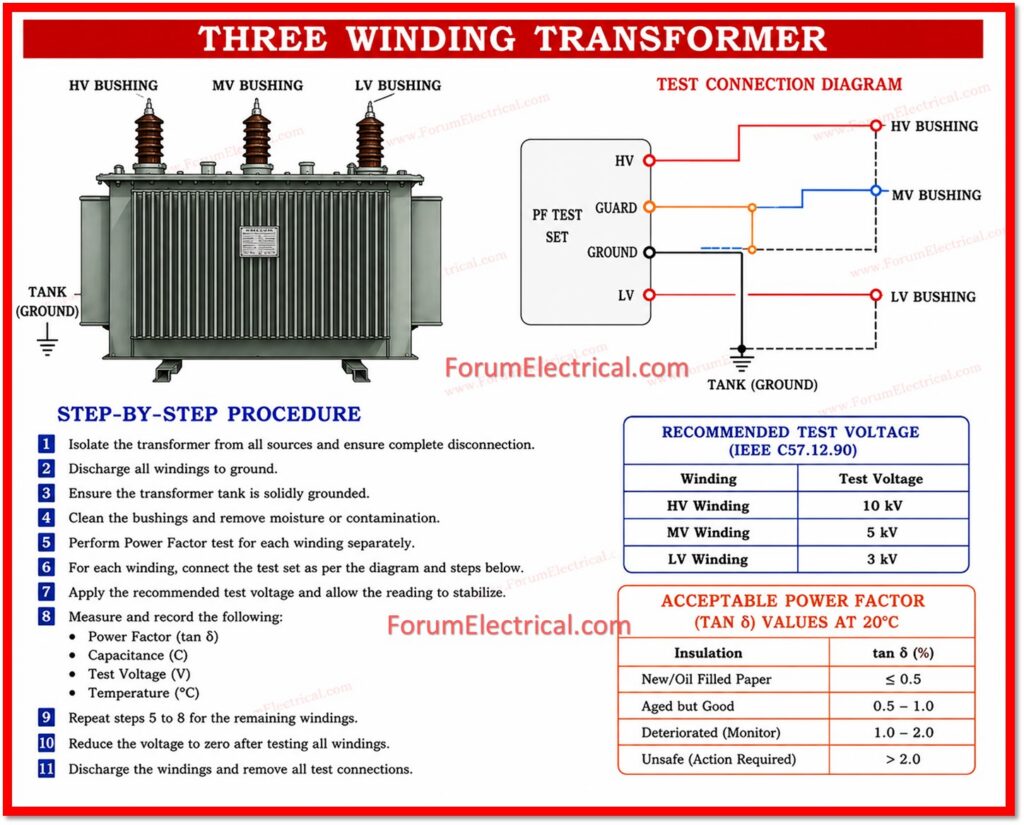
Three-Winding Transformers
Testing is performed in the same manner as two-winding transformers with the addition of tests for the tertiary winding.
If the transformer windings are shielded by a grounded electrostatic shield (or) concentric-winding arrangement, capacitance may appear very low (or) power factor may be negative.
Contact the manufacturer to confirm shield arrangements before interpreting such results.
Autotransformers
In an autotransformer part of the secondary winding is common with the primary.
For testing, short the primary & secondary bushings together & short the tertiary bushings separately.
Test as a two-winding transformer with H+X shorted as one terminal and the tertiary as the second.
Individual bushing tests must be conducted on bushings equipped with test taps.
Wye-Wye Transformers with Non-Separable Neutrals
When a wye-wye (Y-Y) transformer has neutrals that cannot be physically separated, short the high voltage (HV) and low voltage (LV) bushings together and perform a single GST test.
Select a test voltage appropriate for the lower rated winding.
Post-Test Procedure
- Remove all high voltage (HV) and low voltage (LV) test leads from the bushings.
- Reconnect the neutral ground lead that was removed prior to testing.
- Remove all shorting wires from the bushing terminals.
- Reconnect all bushing current transformer (BCT) circuits that were shorted before testing.
- Verify the load tap changer is returned to its normal in-service position if it was moved for testing.
- Conduct a final visual inspection of the transformer & its connections before returning it to service.
- Complete all test record sheets & submit for engineering review & analysis.
Summary
Power factor testing is an important testing in the preventive maintenance for power transformers.
When performed correctly & regularly it provides early warning of insulation degradation due to moisture, contamination, oxidation & aging.
The test is relatively simple to perform but results depend on careful preparation, accurate measurements, thorough documentation and systematic comparison to baseline data.
Always correct power factor readings to 200C and document all ambient conditions at the time of testing and compare results to previous tests (or) manufacturer data.
When results indicate a problem utilize the combination of winding & bushing tests to isolate the fault path before taking corrective action.

 limits, and best practices to detect moisture, contamination and insulation deterioration before transformer failure.)