
Power Factor
The power factor, which is not expressed as a percentage but rather as a per-unit form, is the ratio of true power (in kW) to apparent power (in kVA).
Power Factor = True Power/ Apparent Power
Electric motors are utilized to
- Power fans,
- Pumps,
- Conveyers, and
- Other apparatus in industries
maintains the power factor ratio.

Induction motors are commonly used as electrical drives, but they frequently have poor power factors, which increases the load on cabling and switchgear and reduces electrical supply efficiency.
A 500 kVA transformer is able to provide up to 400 kW, hence the user is only getting an 80% efficiency out of their supply. This is typical power factor for industry, which is around 0.8 lagging.
It is able to recognize the advantage of having a good power factor. By correcting the power factor, these surplus currents can be eliminated. It is accomplished by connecting the capacitors in parallel using the delta connection.
Power Factor Correction (PFC)
The function of power factor correction (PFC) is to increase power factor and thus power quality. It lowers the demands on the distribution system, improves energy efficiency, and lowers electricity bills. It also reduces the probability of device instability and failure.
Power factor correction is accomplished by connecting capacitors that provide reactive energy in opposite to the energy consumed by loads such as motors, which are located locally close to the load. This improves the power factor from the point where the reactive power source is connected, removing unnecessary current flow in the network.
Methods of Power Factor Correction
The methods of power factor correction are,
1). Individual load correction using capacitors
2).Group (or) Bulk using capacitors
3).Automatic switching using capacitors
1). Individual load correction using capacitors
This method involves connecting a capacitor to the load, which is most frequently seen in the installation of fluorescent light fittings. This helps to improve the power factor at the power source. This method is also frequently used with significantly larger motors.

2). Group (or) Bulk using capacitors
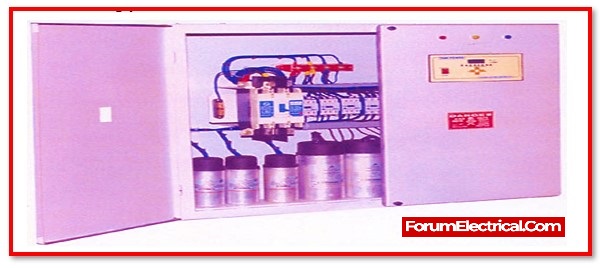
The method described previously might not be very feasible for larger installations. Another possibility is to use a big bank of capacitors, which are then connected to the distribution board supply . These capacitors are then controlled by a timer, which allows them to be attached and disconnected from the supply as needed.
During the most active phase of the time, all of the capacitors would be activated, and then later, they would all be deactivated. It is only permitted to be permanently connected in the installations that have a maximum rating of 25 kVAr.

3). Automatic switching using capacitors
The automatic switching of capacitors is another option that can be used. This is the method that is utilized the majority of the time. It is accomplished by monitoring the reactive power (kVAr) either by electronically (or) through a relay-based form, and when this reaches a particular value, capacitors are stepped in correspondingly and switched in using contactors. This can be done to obtain the desired effect.
Ex: The power factor at the factory that selected was 0.849, which is considered lagging. As a result of taking into consideration the power factor surcharges that would be incurred from the supply company, it can be concluded that it would be in most economic interest to adjust the power factor to the level of 0.98 that was suggested by the supply company. This would free from having to pay the power factor surcharge.
A table containing the loads imposed by the installations is shown
| KW | KVA | KVAr | P.F | |
| 1ØPower | 31390 | 32945.69 | 10004.4 | 0.952 |
| 3ØPower | 138410 | 168165.1 | 95510.1 | 0.823 |
| Total | 169800 | 199913.4 | 105514.5 | 0.849 |
The necessary amount of correction is given as follows:
KVAr = kW (Tanθ1 – Tanθ2)
Total installed load is expressed in kW.
Tanθ1 = the installation’s initial power factor
Tanθ2 = the installation’s new necessary power factor
kW = 169.8 kW
Tanθ1 = cos-1 0.849 = 31.89° tan = 0.622
Tanθ2 = cos-1 0.98 = 11.47° tan = 0.203

kVAr required = kW (Tanθ1 – Tanθ2)
=169.8 (0.622 – 0.203)
= 169.8 (0.419)
= 71.14 kVAr capacitor
Therefore, 71.14 kVAr is the amount of a capacitor needed to change the power factor from the 0.85 lagging to 0.98 lagging. Industries cannot buy a 71.14 kVAr capacitor because they are only made in conventional sizes, such as 10, 25, 50, and 100 kVAr, but a combination of the mentioned could have been utilized. Because switching will be automatic, certain capacitance values must be transferred if the power factor decreases below a predetermined level.

Advantages of PFC-Power Factor Correction
1). Savings on electric bill
Power factor modification lowers reactive energy penalty, reduces kVA demand, and reduces power losses caused in the installation’s transformers and conductors.
2). Increased power availability
Installing PFC technology on the low voltage side of an MV/LV transformer enhances the power available at secondary side. A high-power factor improves the efficiency of an electrical installation by making greater utilization of the components.
3). Reduced installation size
Installing PFC equipment reduces conductor cross-section since the compensated system absorbs less current for same active power.
4).Reduced voltage drops
Installing capacitors reduces voltage drops ahead of the position where the PFC device is connected, minimizing network overload and lowering harmonics.